


10
vacuum breaker is factory-supplied with the unit ventilator
steam coil, and must be field-piped to a location downstream of
the trap to allow vacuum relief when the coil is turned off. In
all situations, the steam piping connected to the unit should be
designed and installed according to good piping practices for
steam systems.
DIRECT EXPANSION REFRIGERANT PIPING
Use the condensing unit manufacturer’s recommended line sizes
and requirements. Perform leak test using nitrogen. Evacuate
and charge per recommended heating, ventilation, and air condi-
tioning (HVAC) procedures and all applicable codes. Insulate
suction line after leak test up to the coil section end plate for cor-
rect operation and to eliminate sweating. Use refrigerant-grade
copper lines only. Units utilizing R-22 refrigerant are
NOT
to be
applied as a heat pump.
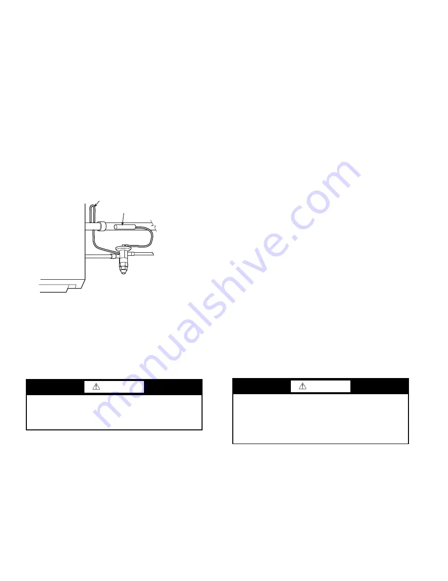
See Fig. 11 for refrigerant piping connections with recommend-
ed locations for the thermostatic expansion valve (TXV) and
sensing bulb. Locate bulb in the horizontal run from approxi-
mately the 9:00 to 3:00 position or in a vertical run.
NOTE: A low limit sensing bulb is factory-installed when a DX
coil is installed.
Fig. 11 — Typical TXV Installation
NOTE: Follow TXV manufacturer’s instructions.
HYDRONIC COIL PIPING
When all joints are complete, perform hydrostatic test for leaks.
Vent all coils at this time. Check interior unit piping for signs of
leakage from shipping damage or mishandling. If leaks are
found, notify a Carrier representative before initiating any re-
pairs. Release trapped air from system (refer to Step 6 —
“Make Final Preparations” on page 31).
Following the hydrostatic test, the installer shall insulate all pip-
ing up to the coil section end plate to prevent condensation
(sweating) and heat loss. Ensure that factory-provided valve
packages are properly insulated. Piping insulation is the respon-
sibility of the installer and should be suitable thickness to prevent
sweating and with adequate vapor barrier.
To ensure compliance with building codes, restore the structure’s
original fire resistance rating by sealing all holes with material
carrying the same fire rating as the structure.
CONTROL VALVES
Controls require normally open heating valves. Chilled water
valves must be piped normally closed. It is recommended that
heating valves fail safe to the open position in all control applica-
tions. Valve packages must always be field insulated to prevent
sweating. See Fig. 12 for piping recommendations.
Step 3 — Make Electrical Connections
Refer to unit serial plate for required supply voltage, fan and
heater amperage and required circuit ampacities. Refer to unit
wiring diagram for unit and field wiring. See Tables 2-4 for elec-
trical data.
Access to all electrical connections can be gained through the ac-
cess panel at the right front side of the unit. See the dimensional
drawings Fig. 3-7 for electrical box connections.
The fan motor should never be controlled by any wiring or de-
vice other than the factory-supplied switch or thermostat/switch
combination unless prior factory authorization is obtained. Fan
motor may be temporarily wired for use during construction only
with prior factory approval and only in strict accordance with the
instructions issued at that time.
All electrical connections should be made by qualified personnel
and be in accordance with governing codes and ordinances. Any
modification of unit wiring without factory authorization will in-
validate all factory warranties and nullify any agency listings.
See Fig. 13-23 for typical wiring connections for basic unit with-
out UV Open controls.
Electric heat elements are the open wire type mounted in indi-
vidual heavy gage galvanized steel frames and suspended in ce-
ramic insulators. Dual capillary type thermal sensing elements,
one automatic reset and one manual, is used to protect the unit
from overheating in the event of abnormal operation. Automatic
reset limit is set at 210°F. The access for the limit switch is locat-
ed on the opposite end of the fan motor. Manual reset high limit
is set at 240°F. The access for the limit switch is located at the
same end as the fan motor.
Step 4 — Mount Actuators (Field-Supplied)
Field-supplied actuators must be mounted on
1
/
2
-in. diameter
damper shafts.
CAUTION
All water coils must be protected from freezing after initial
filling with water. Even if system is drained, unit coils may
still have enough remaining water to cause damage when
exposed to temperatures below freezing.
EQUALIZER
SENSING BULB (CLAMPED TO
SUCTION LINE AND INSULATED)
SUCTION LINE
LIQUID LINE
CAUTION
With factory-installed controls provided by others, factory
may wire controls and actuator based on the request; how-
ever, setting the actuators (switch settings, tightening clamp
to damper shaft, torque pre-loading, etc.) is the sole respon-
sibility of the customer. Failure to set the actuator may
result in equipment damage.


