


75
As a minimum, the following maintenance is required.
1. At least once a year, disconnect the vent piping at the
valve outlet and carefully inspect the valve body and
mechanism for any evidence of internal corrosion or
rust, dirt, scale, leakage, etc.
2. If corrosion or foreign material is found, do not
attempt to repair or recondition. Replace the valve.
3. If the chiller is installed in a corrosive atmosphere or
the relief valves are vented into a corrosive
atmosphere, make valve inspections at more frequent
intervals.
Compressor Bearing Maintenance —
The key to
good bearing maintenance is proper lubrication. Use the proper
grade of oil, maintained at recommended level, temperature,
and pressure. Inspect the lubrication system regularly and
thoroughly.
Excessive bearing wear can be detected through increased
vibration. If this symptom appears, contact an experienced and
responsible service organization to perform vibration analysis
on the compressor.
Compressor Rotor Check —
Use Carrier specified
oil. Excessive compressor rotor wear is shown by a lack of per-
formance. If a lack of performance is noted, have the compres-
sor rotors inspected by a trained service person.
The rotors can be visually inspected once every 5 to
10 years or as needed depending on chiller operating
conditions.
Inspect the Heat Exchanger Tubes
COOLER — Inspect and clean the cooler tubes at the end of
the first operating season. Because these tubes have internal
ridges, a rotary-type tube cleaning system is necessary to fully
clean the tubes. Upon inspection, the tube condition will deter-
mine the scheduled frequency for cleaning, and will indicate
whether water treatment is adequate in the chilled water/
brine circuit. Inspect the entering and leaving chilled water
temperature sensors for signs of corrosion or scale. Replace the
sensor if corroded or remove any scale if found.
CONDENSER — Since this water circuit is usually an open-
type system, the tubes may be subject to contamination and
scale. Clean the condenser tubes with a rotary tube cleaning
system at least once per year and more often if the water is con-
taminated. Inspect the entering and leaving condenser water
sensors for signs of corrosion or scale. Replace the sensor if
corroded or remove any scale if found.
Higher than normal condenser pressures, together with the
inability to reach full refrigeration load, usually indicate dirty
tubes or air in the chiller. If the refrigeration log indicates a rise
above normal condenser pressures, check the condenser refrig-
erant temperature against the leaving condenser water tempera-
ture. If this reading is more than what the design difference is
supposed to be, then the condenser tubes may be dirty or water
flow may be incorrect. Because HCFC-22 and HFC-134a are
high-pressure refrigerants, air usually does not enter the chiller;
instead the refrigerant leaks out.
During the tube cleaning process, use brushes especially de-
signed to avoid scraping and scratching the tube wall. Contact
your Carrier representative to obtain these brushes. Do not use
wire brushes.
Water Leaks —
Water is indicated during chiller opera-
tion by the refrigerant moisture indicator on the refrigerant mo-
tor cooling line. See Fig. 11 and 12. Water leaks should be re-
paired immediately.
Water Treatment —
Untreated or improperly treated wa-
ter may result in corrosion, scaling, erosion, or algae. The ser-
vices of a qualified water treatment specialist should be ob-
tained to develop and monitor a treatment program.
Inspect the Starting Equipment —
Before working
on any starter, shut off the chiller, and open all disconnects sup-
plying power to the starter.
Hard scale may require chemical treatment for its preven-
tion or removal. Consult a water treatment specialist for
proper treatment.
Chiller must be dehydrated after repair of water leaks. See
Chiller Dehydration section, page 58.
Water must be within design flow limits, clean, and treated
to ensure proper chiller performance and to reduce the
potential of tubing damage due to corrosion, scaling, ero-
sion, and algae. Carrier assumes no responsibility for
chiller damage resulting from untreated or improperly
treated water.
The disconnect on the starter front panel does not deener-
gize all internal circuits. Open all internal and remote dis-
connects before servicing the starter.
Never open isolating knife switches while equipment is
operating. Electrical arcing can cause serious injury.
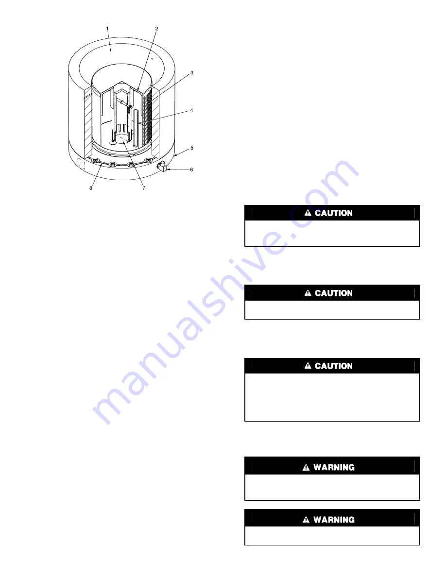
LEGEND
Fig. 40 — 23XL Float Valve Design
1
— Refrigerant Inlet from FLASC Chamber
2
— Linear Float Assembly
3
— Float Screen
4
— Bubble Line
5
— Float Cover
6
— Bubble Line Connection
7
— Refrigerant Outlet to Cooler
8
— Gasket
Содержание 23XL
Страница 18: ...18 Fig 15 Control Panel Fig 16 Power Panel ...
Страница 51: ...51 Fig 31 23XL Leak Test Procedure ...
Страница 52: ...52 Fig 32 Typical Optional Pumpout System Piping Schematic with Storage Tank TC Frame 1 and 2 Chillers ...
Страница 53: ...53 Fig 33 Typical Optional Pumpout System Piping Schematic With Storage Tank TD Frame 4 Chillers ...
Страница 54: ...54 Fig 34 Typical Optional Pumpout System Piping Schematic Without Storage Tank TC Frame 1 and 2 Chillers ...
Страница 55: ...55 Fig 35 Typical Optional Pumpout System Piping Schematic Without Storage Tank TD Frame 4 Chillers ...
Страница 99: ...99 Fig 49 Benshaw Inc Solid State Unit Mounted Starter Wiring Schematic Low Voltage ...


