


46
When the ATTACH TO NETWORK DEVICE screen is ac-
cessed, information can not be read from the CVC on any de-
vice until one of the devices listed on that screen is attached.
The CVC erases information about the module to which it was
attached to make room for information on another device.
Therefore, a CCN module must be attached when this screen is
entered.
To attach any CCN device, highlight it using the
softkey and press the
softkey. The message “UP-
LOADING TABLES, PLEASE WAIT” displays. The CVC
then uploads the highlighted device or module. If the module
address cannot be found, the message “COMMUNICATION
FAILURE” appears. The CVC then reverts back to the AT-
TACH TO DEVICE screen. Try another device or check the
address of the device that would not attach. The upload process
time for each CCN module is different. In general, the upload-
ing process takes 1 to 2 minutes. Before leaving the ATTACH
TO NETWORK DEVICE screen, select the local device. Oth-
erwise, the CVC will be unable to display information on the
local chiller.
ATTACHING TO OTHER CCN MODULES — If the chill-
er CVC has been connected to a CCN Network or other PIC
controlled chillers through CCN wiring, the CVC can be used
to view or change parameters on the other controllers. Other
PIC II chillers can be viewed and set points changed (if the oth-
er unit is in CCN control), if desired, from this particular CVC
module.
If the module number is not valid, the “COMMUNICA-
TION FAILURE” message will show and a new address num-
ber must be entered or the wiring checked. If the module is
communicating properly, the “UPLOAD IN PROGRESS”
message will flash and the new module can now be viewed.
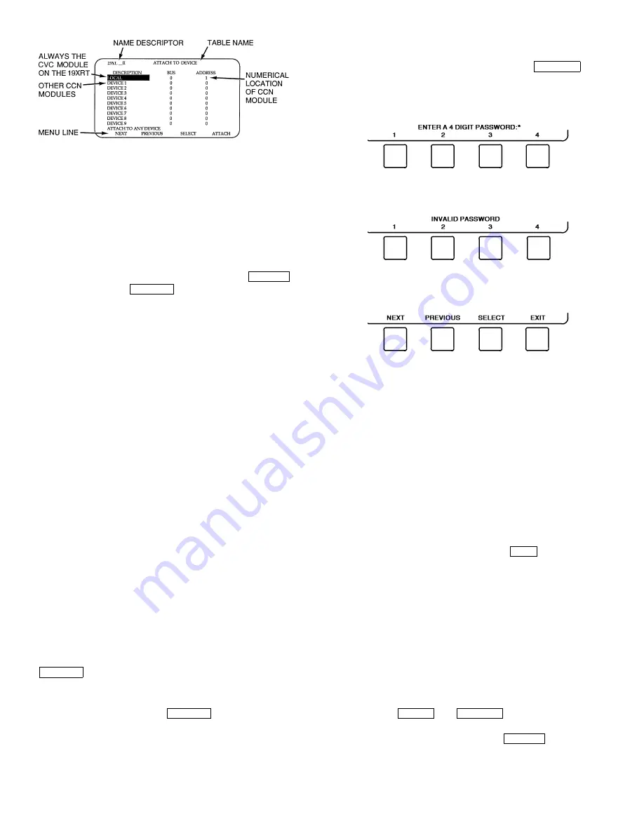
Whenever there is a question regarding which module on
the CVC is currently being shown, check the device name de-
scriptor on the upper left hand corner of the CVC screen. See
Fig. 27.
When the CCN device has been viewed, the ATTACH TO
NETWORK DEVICE table should be used to attach to the PIC
that is on the chiller. Move to the ATTACH TO NETWORK
DEVICE table (LOCAL should be highlighted) and press the
softkey to upload the LOCAL device. The CVC
for the 23XL will be uploaded and default screen will display.
NOTE: The CVC will not automatically reattach to the local
module on the chiller. Press the
softkey to attach to
the LOCAL device and view the chiller operation.
Service Operation —
An overview of the tables and
screens available for the SERVICE function is shown in
Fig. 21.
TO ACCESS THE SERVICE SCREENS — When the SER-
VICE screens are accessed, a password must be entered.
1. From the main MENU screen, press the
softkey. The softkeys now correspond to the numerals
1, 2, 3, 4.
2. Press the four digits of the password, one at a time. An
asterisk (*) appears as each digit is entered.
NOTE: The initial factory-set password is 1-1-1-1.
If the password is incorrect, an error message is
displayed.
If this occurs, return to Step 1 and try to access the
SERVICE screens again. If the password is correct, the
softkey labels change to:
NOTE: The SERVICE screen password can be changed by
entering the CVC CONFIGURATION screen under SERVICE
menu. The password is located at the bottom of the menu.
The CVC screen displays the following list of available
SERVICE screens:
•
Alarm History
•
Control Test
•
Control Algorithm Status
•
Equipment Configuration
•
ISM (Starter) Config Data
•
Equipment Service
•
Time and Date
•
Attach to Network Device
•
Log Out of Device
•
CVC Configuration
See Fig. 21 for additional screens and tables available from
the SERVICE screens listed above. Use the
softkey to
return to the main MENU screen.
NOTE: To prevent unauthorized persons from accessing the
CVC service screens, the CVC automatically signs off and
password-protects itself if a key has not been pressed for
15 minutes. The sequence is as follows. Fifteen minutes after
the last key is pressed, the default screen displays, the CVC
screen light goes out (analogous to a screen saver), and the
CVC logs out of the password-protected SERVICE menu.
Other screen and menus, such as the STATUS screen can be
accessed without the password by pressing the appropriate
softkey.
TO LOG OUT OF NETWORK DEVICE — To access this
screen and log out of a network device, from the default CVC
screen, press the
and
softkeys. Enter the
password and, from the SERVICE menu, highlight LOG OUT
OF NETWORK DEVICE and press the
softkey.
The CVC default screen will now be displayed.
HOLIDAY SCHEDULING (Fig. 28) — The time schedules
may be configured for special operation during a holiday peri-
od. When modifying a time period, the “H” at the end of the
SELECT
ATTACH
ATTACH
ATTACH
SERVICE
EXIT
MENU
SERVICE
SELECT
Fig. 27 — Example of Attach to Network
Device Screen
Содержание 23XL
Страница 18: ...18 Fig 15 Control Panel Fig 16 Power Panel ...
Страница 51: ...51 Fig 31 23XL Leak Test Procedure ...
Страница 52: ...52 Fig 32 Typical Optional Pumpout System Piping Schematic with Storage Tank TC Frame 1 and 2 Chillers ...
Страница 53: ...53 Fig 33 Typical Optional Pumpout System Piping Schematic With Storage Tank TD Frame 4 Chillers ...
Страница 54: ...54 Fig 34 Typical Optional Pumpout System Piping Schematic Without Storage Tank TC Frame 1 and 2 Chillers ...
Страница 55: ...55 Fig 35 Typical Optional Pumpout System Piping Schematic Without Storage Tank TD Frame 4 Chillers ...
Страница 99: ...99 Fig 49 Benshaw Inc Solid State Unit Mounted Starter Wiring Schematic Low Voltage ...


