5–9
T-375
5. Install the new heater with a new gasket on either side.
6. Assemble transition to heater and torque mounting hardware (refer to engine manual for torque values).
7. Reconnect the harness to heater connection point.
8. Coat the stud on the heater with protective coating.
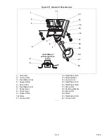
5.4.15
Intake Heater Switch (HS)
1. Remove the control box cover.
2. Remove all connections going to the Heater Switch (HS).
3. Remove the Heater Switch (HS) from the control box.
4. Install the new Heater Switch (HS).
5. Reconnect the wire harness connections to the switch.
6. Confirm wires are connected to the correct terminals.
7. Reinstall the control box cover.
5.5 Servicing the AC Generator
5.5.1
Remove and Replace Procedure
The only serviceable parts on the generator are the torsional dampener, key, fan, and fan cover. If there is a
problem with the generator, it should be replaced using the following procedure.
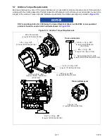
For Unidrive torque requirements, see
Procedure:
1. Remove the unit top and side panels in order to access the generator.
2. Disconnect the battery.
CAUTION
!
Observe proper polarity when installing the battery or connecting a battery charger, the nega
-
tive battery terminal must be grounded. Reverse polarity may damage the charging system.
When charging the battery in unit, isolate the battery by disconnecting the negative battery ter
-
minal first, then the positive. Once the battery has been charged, connect the positive battery
terminal first, then the negative.
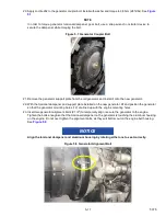
3. Remove the truss assembly center nuts and nut plate.
4. Remove the truss side bolts / washers and spacers (2), and remove the truss.
5. Remove the 3/8” bolt / washer that secures the wire harnesses and fuel lines to the top of the generator.
Move the wire harnesses and fuel lines out of the way.
6. Remove the 1/4” bolts / washers (4) that secure the battery charger bracket to the unit frame. This will allow
you to access the cables on the bottom of the battery charger.
7. Mark and disconnect the cables on the battery charger and remove the battery charger assembly from the
unit.
8. Remove the bolts / washers (6) that secure the receptacle box to the unit. Wire-tie the receptacle box to the
side of the unit so that the receptacle box is not hanging by the cables.
9. Remove the tape on the wire harness and cut the wires (5) that connect the receptacle box to the generator.
Make sure to cut the wires on the receptacle box side of the current butt splices.
10. Remove the bolts / washers (2) that secure the generator support plate to the two generator shockmounts.
11. Remove the bolts / washers (3) that secure the lower radiator access panel (on the other side of the unit) in
order to access the engine shockmounts.
Содержание 69UG15
Страница 2: ......
Страница 4: ......
Страница 12: ......
Страница 32: ......
Страница 40: ......
Страница 58: ......
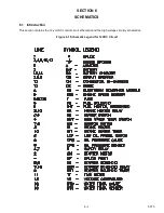
Страница 60: ...T 375 6 2 Figure 6 2 Schematic for 12 VDC Control Circuit 12 VDC Control Circuit ...
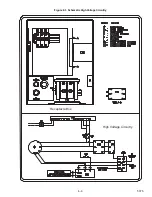
Страница 61: ...6 3 T 375 Figure 6 3 Schematic High Voltage Circuitry High Voltage Circuitry Receptacle Box ...
Страница 62: ......
Страница 65: ......

