


2–11
T-375
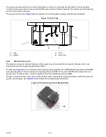
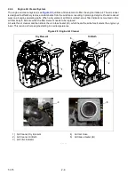
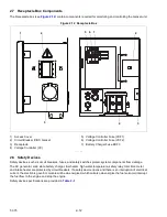
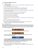
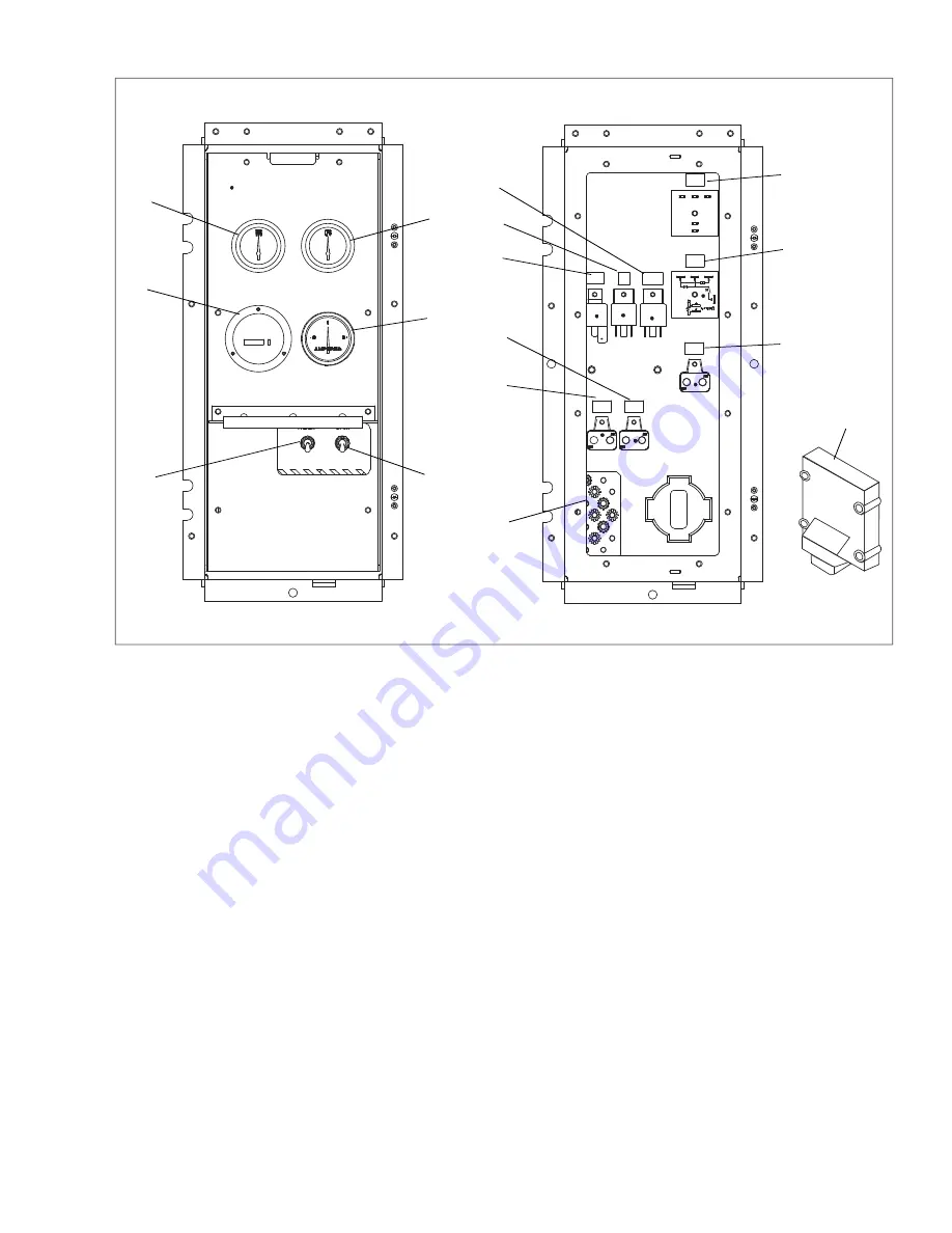
Figure 2.11 Control Panel and Control Box
1) Water Temperature Gauge
2) Oil Pressure Gauge
3) Total Time Meter (TT)
4) Ammeter (A)
5) Intake Heater Switch (HS)
6) Ignition Switch (IGN)
7) Starter Solenoid Relay (SSR)
8) Safety Relay (S)
9) Intake Heater Relay (HR)
10) Circuit Breaker (CB2)
11) Circuit Breaker (CB3)
12) Circuit Breaker (CB4)
13) Starter Solenoid Timer (SST)
14) Intake Heater Timer (IHT)
15) Ground Studs
16) Electronic Governor Module (EG)
- - - - -
SST
HR
S
SSR
IHT
CB2
CB3
CB4
OFF
OFF
RUN
INTAKE AIR HEATER IGNITION
3
2
4
5
15
10
12
7
9
8
11
16
Mounted to
back of box
1
Control Panel
Control Box
13
14
6
Содержание 69UG15
Страница 2: ......
Страница 4: ......
Страница 12: ......
Страница 32: ......
Страница 40: ......
Страница 58: ......
Страница 60: ...T 375 6 2 Figure 6 2 Schematic for 12 VDC Control Circuit 12 VDC Control Circuit ...
Страница 61: ...6 3 T 375 Figure 6 3 Schematic High Voltage Circuitry High Voltage Circuitry Receptacle Box ...
Страница 62: ......
Страница 65: ......