background image

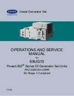
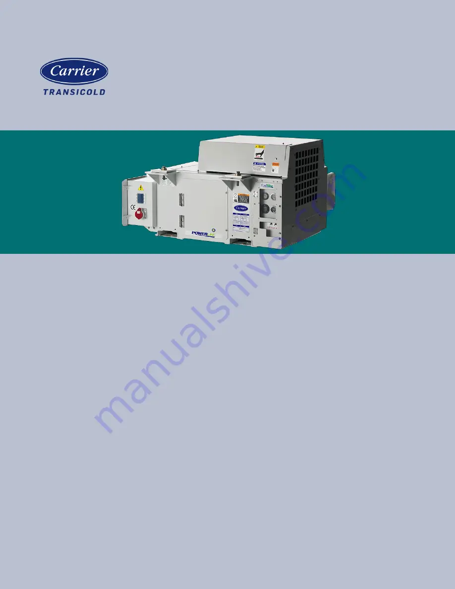
Diesel Generator Set

OPERATIONS AND SERVICE 

MANUAL

For

69UG15

PowerLINE

®

 Series 55 Generator Set Units

PID UG5500 to 5599

EU Stage V Compliant

T-375

Содержание 69UG15

Страница 1: ...Diesel Generator Set OPERATIONS AND SERVICE MANUAL For 69UG15 PowerLINE Series 55 Generator Set Units PID UG5500 to 5599 EU Stage V Compliant T 375 ...

Страница 2: ......

Страница 3: ...OPERATIONS AND SERVICE MANUAL For 69UG15 PowerLINE Series 55 Generator Set Units PID UG5500 to 5599 EU Stage V Compliant Carrier Corporation 2021 Printed in U S A March 2021 ...

Страница 4: ......

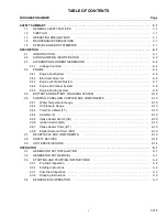
Страница 5: ...tem 2 9 2 5 BATTERY AND BATTERY CHARGING SYSTEM 2 10 2 6 CONTROL PANEL AND CONTROL BOX COMPONENTS 2 10 2 6 1 Water Temperature Gauge 2 10 2 6 2 Oil Pressure Gauge 2 10 2 6 3 Total Time Meter TT 2 10 2 6 4 Ammeter A 2 10 2 6 5 Intake Heater Switch HS 2 10 2 6 6 Ignition Switch IGN 2 10 2 6 7 Intake Heater Timer IHT 2 10 2 6 8 Starter Solenoid Timer SST 2 10 2 7 RECEPTACLE BOX COMPONENTS 2 12 2 8 SA...

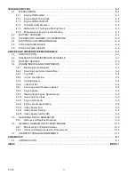
Страница 6: ...NENTS 5 3 5 4 1 Bleeding the Fuel System 5 3 5 4 2 Servicing Fuel Pump Internal Filter 5 3 5 4 3 Fuel Filter 5 4 5 4 4 In Line Fuel Strainer 5 4 5 4 5 Cooling System 5 4 5 4 6 Lube Oil Filter 5 4 5 4 7 Servicing Low Oil Pressure Switch 5 4 5 4 8 Engine Speed 5 5 5 4 9 Replacing the Engine Speed Sensor 5 5 5 4 10 Servicing Poly V belt 5 5 5 4 11 Engine Air Cleaner 5 5 5 4 12 Engine Crankcase Breath...

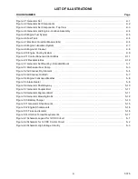
Страница 7: ... 3 1 Generator Set Mounting Standard Mount 3 1 Figure 5 1 Mechanical Fuel Pump 5 3 Figure 5 2 Air Cleaner Dry Element 5 6 Figure 5 3 Air Cleaner Oil Bath 5 7 Figure 5 4 Engine Crankcase Breather 5 8 Figure 5 5 Intake Heater 5 8 Figure 5 6 Generator Shaft Keyway 5 10 Figure 5 7 Generator Coupler Bolt 5 11 Figure 5 8 Generator Alignment Bolt 5 11 Figure 5 9 Generator Mounting Bolts 5 12 Figure 5 10 ...

Страница 8: ...Engine Starts Then Stops 4 2 Table 4 3 Engine Will Not Shut Off 4 2 Table 4 4 Starter Motor Malfunction 4 2 Table 4 5 Malfunction In The Engine Starting Circuit 4 3 Table 4 6 Miscellaneous Engine Troubleshooting 4 3 Table 4 7 Battery Charger Solid State 4 4 Table 4 8 Alternating Current Generator 4 5 Table 4 9 Electronic Governor Modules 4 6 Table 4 10 Voltage Controller 4 6 Table 5 1 Preventative...

Страница 9: ...y terminal has been disconnected Always work in pairs Never work on the equipment alone In case of severe vibration or unusual noise stop the unit and investigate 1 4 Maintenance Precautions Be sure power is turned off and the negative battery cable is disconnected before working on generator set Do not bypass any electrical safety devices e g bridging an overload or using any sort of jumper wires...

Страница 10: ...sulation of this generator winding may be safely checked by using a meg ger A high megger reading indicates good insulation CAUTION Observe proper polarity when installing the battery or connecting a battery charger the nega tive battery terminal must be grounded Reverse polarity may damage the charging system When charging the battery in unit isolate the battery by disconnecting the negative batt...

Страница 11: ...eaner is being serviced CAUTION Do not underfill or overfill the oil bath cups Overfilling of cups causes loss of capacity under filling cups causes lack of filtering efficiency CAUTION Continued operation with failed shockmounts may result in engine or generator damage ...

Страница 12: ......

Страница 13: ... in a structural steel frame The engine is a vertical in line four cylinder diesel manufactured by Kubota The generator is a 15 kW permanent single winding dual bearing type that supplies nominal 50 60Hz power Electrical controls are mounted in a control box with operating controls and gauges mounted on a control panel which also serves as the control box cover The control panel components are pro...

Страница 14: ...rts identification number PID The model number identifies the overall configuration while the PID provides information on specific optional equipment and differences in detailed parts Figure 2 2 Generator Set Components 1 Fuel Tank 2 Battery 3 Battery Charger 4 AC Generator 5 Engine 6 Exhaust Muffler 7 Engine Air Cleaner 8 Fuel Filter Water Separator 9 Oil Filter 10 Receptacle Box 11 Control Panel...

Страница 15: ...ents Top View 1 Fuel Tank 2 Battery 3 Battery Charger 4 AC Generator 5 Engine 6 Exhaust Muffler 7 Air Cleaner 8 Fuel Filter Water Separator 9 Oil Filter 10 Receptacle Box 11 Control Panel and Control Box 12 Radiator 1 2 3 4 5 6 7 8 9 10 11 12 ...

Страница 16: ...ly loaded 2 3 1 Voltage Controller The Voltage Controller VC maintains ISO voltage via two speed and single winding control It is used to regulate voltage in order to keep the generator output within ISO limits see Table 2 3 The Voltage Controller and Voltage Controller fuses VCF1 and VCF2 are located in the receptacle box see Figure 2 12 2 4 Engine The engine see Figure 2 4 is a vertical in line ...

Страница 17: ...filter water separator also contains a 12 volt fuel heater to heat the fuel Low pressure fuel then enters the injection pump where it is compressed to higher pressures and distributed to individual fuel lines that supply an injector nozzle for each cylinder The injector nozzles spray atomized fuel into the combustion chamber based on the tim ing of the injector pump Any excess fuel in the nozzles ...

Страница 18: ...nor controls the speed of the engine by using an Electronic Governor Module EG Fuel Solenoid FS and an Engine Speed Sensor ESS The EG see Figure 2 7 is a solid state control module pre programmed for 1800 RPM high speed and 1500 RPM low speed operation The EG receives an input signal from the ESS of the current RPM and compares this to a preset value The EG sends a correction signal to the FS to m...

Страница 19: ... wear The engine lubricating oil filter is mounted in a horizontal arrangement The Oil Pressure Sender OPS located at the oil filter housing senses lube oil pressure and transmits a signal to the Oil Pressure Gauge located on the con trol panel see Figure 2 11 The Low Oil Pressure LOP switch opens when engine lubricating oil pressure is observed below 1 27 kg cm Figure 2 8 Engine Lubrication Syste...

Страница 20: ... a dry element air filter is utilized an air filter indicator is mounted on the air filter body to indicate when the filter element needs to be replaced Air exits the air cleaner and then enters the air intake heater IH which heats the air before it enters the engine cyl inder This is done to help engine starting in cold temperatures Figure 2 9 Engine Air Cleaner 1 Air Cleaner Dry Element 2 Air Cl...

Страница 21: ...ant to the surrounding air The water pump and the radiator cooling fan are belt driven from the engine crankshaft The High Water Temperature Switch HWT and Water Temperature Sender WTS monitor and regulate cooling water temperature Figure 2 10 Engine Cooling System 1 Radiator Assembly 2 Radiator Fill Cap 3 Coolant Recovery Bottle 4 High Water Temperature Switch HWT 5 Water Temperature Sender WTS 1...

Страница 22: ... the Oil Pressure Gauge 2 6 3 Total Time Meter TT The Total Time Meter TT calculates the total hours the unit has been running which provides an accurate readout of accumulated engine running time This data can be used to establish proper maintenance schedules refer to Table 5 1 2 6 4 Ammeter A The Ammeter indicates the rate of charge or discharge of the battery charging system The battery chargin...

Страница 23: ... Solenoid Relay SSR 8 Safety Relay S 9 Intake Heater Relay HR 10 Circuit Breaker CB2 11 Circuit Breaker CB3 12 Circuit Breaker CB4 13 Starter Solenoid Timer SST 14 Intake Heater Timer IHT 15 Ground Studs 16 Electronic Governor Module EG SST HR S SSR IHT CB2 CB3 CB4 OFF OFF RUN INTAKE AIR HEATER IGNITION 3 2 4 5 15 10 12 7 9 8 11 16 Mounted to back of box 1 Control Panel Control Box 13 14 6 ...

Страница 24: ...Safety devices such as circuit breakers fuses and safety switches protect system components from damage The AC generator solid state battery charger fuel heater high water temperature safety relay total time meter and intake heater are protected by circuit breakers If a safety device opens and there is an interruption of electrical current the electronic governor module will be de energized which ...

Страница 25: ...r module Safety Switch Fuse 1 2 3 replace Switch Setting Trips at 10 amps Intake Heater Unsafe Condition Excessive current draw on intake heater circuit Safety Switch Circuit breaker CB 3 Automatic reset Switch Setting Trips at 50 amps Battery Charger Unsafe Condition Excessive current draw on 12 volt supply circuit Safety Switch Circuit breaker CB 4 Automatic reset Switch Setting Trips at 50 amps...

Страница 26: ... Gallon Aluminum 698 1 kg 65 Gallon Steel 741 2 kg Table 2 3 Generator Output 15 KW 18 75 KVA 0 8 pf KW Output Voltage 400 500 VAC 60 hz 360 460 VAC 50 hz Speed 1800 RPM 60 hz 1500 RPM 50 hz Weight 121 kg Part Number 54 00738 20 Table 2 4 Engine Data Bore Stroke 83 mm 102 4 mm Compression Ratio 22 0 to 1 Cylinders Number Four Displacement 2 22 liters 2216 cm3 Firing Order 1 3 4 2 Screw Threads All...

Страница 27: ...rade 18 C to 7 C SAE 10W30 or Mobile Delvac 1 Centigrade 7 C and above SAE 10W30 or 15W40 or Mobile Delvac 1 Mobile Delvac 1 5W 40 or 15W 40 is the only approved synthetic oil Fuel and Fuel Heater Thermostat FHT Fuel Winter Diesel No 2 with winter blends Summer Diesel No 2 FHT Winter Close on temperature fall 7 2 3 6 C Summer Open on temperature rise 23 8 3 6 C Power Consumption 150 Watts 10 at 14...

Страница 28: ...LC and deionized water This mixture provides protection to 37 C For replacement use Shell Rotella ELC Nitrite Free Pre Diluted 50 50 antifreeze coolant Water Temperature Safety Switch Setting Opens 110 3 C Resets 93 C minimum Thermostat Starts to open 80 to 84 C Fully open 95 C Low Coolant Sensor Opens Loss of 907g of coolant or more Closes Refilling of radiator to proper level Table 2 4 Engine Da...

Страница 29: ...n the unit and fork truck 3 Center the generator under the chassis slide mounting plates fully onto the chassis I beams and torque mounting bolts to 11 1 12 4 m kg Upon completion remove the safety chain before removing forks of fork lift truck from the unit 3 2 Generator Set Removal 1 Disconnect power cable to generator if connected 2 With fork lift in position and safety chain attached slide mou...

Страница 30: ...ceed to Starting Instructions see Section 3 3 2 3 3 2 Starting Instructions Before start up both the Genset Circuit Breaker CB1 and the refrigerated unit should be OFF After start up the Genset unit should be run for at least two minutes to allow the power source to stabilize before supplying power to the refrigerated unit This will eliminate the potential of any cold start transient spikes from r...

Страница 31: ...is on the ammeter will show a 42 amp draw A second set of contacts also energizes the Safety Relay S If the High Water Temperature Switch HWT opens to break the safety relay ground connection the Safety Relay S will not energize and the engine will not start To start the engine the Ignition Switch IGN is held in the START position With the switch in the START position current flows to the Starter ...

Страница 32: ......

Страница 33: ...oil Table 2 4 Fuse F5 is bad Replace Starter motor cranks but fails to start No fuel in tank Table 2 4 Air inside the fuel system Section 5 4 1 Water inside the fuel system Drain Sump Plugged fuel filters Replace Air intake heater is bad Section 5 4 13 Low oil oil pressure switch defective Section 5 4 7 Faulty heater switch Section 5 4 14 Plugged fuel lines to injector s Engine Manual Mechanical l...

Страница 34: ...l low oil pressure switch defective Section 5 4 7 Leak in fuel system Check Injector nozzle s defective Engine Manual Injection pump defective Engine Manual Generator internal overloads open Table 2 3 Table 4 3 Engine Will Not Shut Off Condition Possible Cause Remedy Reference Section Engine will not shut off Loose ground connection Clean Tighten Improperly seated fuel solenoid Correct Table 4 4 S...

Страница 35: ...n energized Battery defective Correct Loose electrical connections Tighten Oil pressure switch defective Section 5 4 7 Water temperature safety switch open Section 5 4 5 Fuel solenoid defective Engine Manual Intake heater switch is bad Check Engine Manual Electronic Governor Module EG is bad Replace Section 5 4 14 Check Replace Intake heater does not energize Intake heater switch is bad Section 5 ...

Страница 36: ...r Locate and remove short or replace charger Circuit breaker trips repeatedly even when not connected Internal short Replace charger Charger does not taper back after charging for a few minutes Bad cell in battery Test battery for defect according to battery manufacturer s instructions Charger is bad Replace Charger does not charge Open BCF3 Replace Charger is not receiving AC input Use voltmeter ...

Страница 37: ...ed by flickering lights Fluctuating speed Section 5 4 8 Irregular speed of engine Engine Manual Loose terminal or load connections Tighten Bad bearing causing uneven air gap Replace High voltage Excessive engine speed Section 5 4 8 Overheating Generator overloaded Check Clogged vents baffles Check Clean High temperature surrounding generator Section 5 4 5 Insufficient air circulation or recirculat...

Страница 38: ...ules Fault LED flash code Possible Cause Engine Over Speed more than 2 530 RPM One Long One Short ESS or mechanical engine problem Actuator Wiring Disconnection No signal from ESS for 2 seconds after RPM is greater than 1 000 RPM for 10 seconds OR for 5 seconds while engine cranking no voltage at EG pin 18 Two Long One Short Short ESS or wiring problem Speed Sensor Disconnection Fuel speed actuato...

Страница 39: ... if not running Blown Fuse Replace Verify Voltage Controller has power powered by high voltage verify green light is illuminated Faulty Voltage Controller Loose connections Faulty Generator Replace and tighten Verify Voltage Controller has green light illuminated and yellow light flashing at 1 Hz Yellow light flashing sequence other than at 1 Hz indicates a fault condition One Long Two Short Volta...

Страница 40: ......

Страница 41: ...ction X 4 Check Poly V belt for fraying or cracking replace as required Section 5 4 10 X X X 5 Check radiator hoses for leaks X X X 6 Check coolant level add 50 50 mix as required Section X X X 7 Check radiator coil and generator air intake for cleanliness Section 5 4 5 X X X 8 Check Air Cleaner X X X For Dry element air cleaner Check for cleanliness and clean replace as filter indicator indicates...

Страница 42: ...ck water pump bearing end play Engine Manual X X 23 Change fuel filter Section 5 4 3 X X 24 Check crankcase breather Section 5 4 12 X X 25 Remove and check engine generator shockmounts for cracks cuts abrasion or flaring Section 5 6 2 X X 26 Clean and flush coolant system Section 5 4 5 X 27 Check starter condition Engine Manual X X 28 Check engine compression Engine Manual X X 29 Check and adjust ...

Страница 43: ...the manual plunger until a positive pressure resistance is felt This will indicate fuel flow 3 Depress and turn the top of the manual priming pump clockwise to lock in place 4 Start the engine see Section 2 4 5 When the engine is running properly turn the fuel bleed valve clockwise until fully closed 5 4 2 Servicing Fuel Pump Internal Filter The internal fuel filter may become plugged or restricte...

Страница 44: ...lant completely by opening the drain cock and removing the radiator cap CAUTION Never pour cold water into a hot engine 3 Close the drain cock and fill the system with clean untreated water to which between 3 and 5 of an alkaline base radiator cleaner should be added 170 grams dry 151 grams to 3 8 liter of water 4 Run the engine 6 to 12 hours and drain the system while warm Rinse the system three ...

Страница 45: ...driven by a sheave on the engine crankshaft Its two functions are 1 to drive the radiator fan and 2 to drive the water pump To replace the poly V belt perform the following steps 1 Using the proper size socket slowly rotate the crank on the crank pulley nut At the same time use a flat blunt object to guide the belt off the crank pulley towards radiator Be careful not to damage grooves on the pulle...

Страница 46: ...move air cleaner bottom cap 2 Remove the air filter element from the air cleaner body 3 Install the new element secure the bottom cap with the cap clamps Figure 5 2 Air Cleaner Dry Element 1 Air Outlet 2 Air Cleaner Body 3 Air Inlet 4 Cap Clamp 5 Air Outlet 6 Air Filter Indicator Air Cleaner Oil Bath Service See Figure 5 3 for this procedure The oil cup should be inspected during pretrip before ea...

Страница 47: ...p is serviced If there is any sign of contaminant buildup or plugging the air cleaner body should be removed and back flushed At least once a year or at regular engine service intervals remove the entire air cleaner and perform the following cleaning procedure 1 Remove oil cup Check and clean center tube WARNING Do not use gasoline to clean air cleaner parts 2 Pump solvent through the air outlet w...

Страница 48: ... 4 Breather Cover 5 Bleed Hole 5 4 13 Intake Heater Test 1 Disconnect the lead from the heater terminal 2 Measure the resistance between the heater positive terminal and the heater body 3 If the resistance is infinity or significantly different than the specification resistance cold 0 3 ohms replace the heater Figure 5 5 Intake Heater 1 Positive Terminal 2 Heater Body 5 4 14 Intake Heater Service ...

Страница 49: ... system When charging the battery in unit isolate the battery by disconnecting the negative battery ter minal first then the positive Once the battery has been charged connect the positive battery terminal first then the negative 3 Remove the truss assembly center nuts and nut plate 4 Remove the truss side bolts washers and spacers 2 and remove the truss 5 Remove the 3 8 bolt washer that secures t...

Страница 50: ... the fan hits the radiator coil 15 Starting with the lower bolts remove the 3 8 16 bolts washers 12 that secure the generator to the engine NOTICE Although the generator torsional dampener and flywheel adapter plate will normally keep the generator coupled to the engine even without the bolts it is safest to remove the lower generator bolts first in case the generator shifts and falls during bolt ...

Страница 51: ...mpener and support plate installed on the new generator lift and position the generator so that the generator mounting holes 12 are lined up with the engine mounting holes 23 Insert two generator alignment bolts 2 1 2 to temporarily align secure the generator to the engine Tighten the bolts enough so that the torsional dampener on the generator is touching the aluminum housing on the engine Do not...

Страница 52: ...ounting bolts 2 down into the generator support plate in order to line up the mounting bolt holes with the shockmounts 28 Ensure that the large washers placed on the shockmounts and slowly lower the generator engine so that the generator support plate holes line up with the shockmount holes 29 Remove the generator support plate bolts and install the bolts large washers from the bottom of the shock...

Страница 53: ...onto the top of the generator secure with the bolt 41 Replace the truss and the truss brackets secure the sides with the mounting bolts 2 See Figure 5 13 NOTE Installing the two back truss bolts first allows the truss assembly to be pulled forward slightly making it easier to install the two front truss bolts 42 Secure the center of the truss to the isolator by installing the nuts 2 and nut plate ...

Страница 54: ...ve truss unidrive isolator and all hardware as shown in Figure 5 13 3 Remove all hardware as shown in Figure 5 12 4 Raise the engine just enough to remove the shockmounts as shown in Figure 5 12 5 Install new shockmounts 6 Lower the engine enough to assemble hardware as shown and torque per Section 5 7 7 Remove chains from the lift eyes Generator Shockmount Replacement 1 Use the two lift eyes to l...

Страница 55: ...7 Shockmount 8 Shockmount 9 Support Plate 10 Frame 11 Locknut 5 8 12 Flat Washer 5 8 13 Mounting Base 14 Locknut 1 2 15 Flat Washer 1 2 16 Flat Washer 5 8 17 Screw 5 8 18 Snubbing Washer 19 Screw 1 2 20 Frame 21 Flat Washer 3 8 22 Locknut 3 8 1 17 10 13 20 16 11 14 15 7 4 18 19 5 21 22 Install Mount with Large Flare at Top 2 12 3 8 9 6 ...

Страница 56: ...ing Washer 3 Bolt 4 Lock Washer 5 Snubbing Washer 6 Shockmount 7 Flat Washer Figure 5 13 Truss and Isolator 1 Truss 2 Bolt 3 Lock Washer 4 Flat Washer 5 Frame 6 Unidrive 7 Locknut 8 Heat Shield 9 Isolator 10 Nutplate 11 Truss 3 4 5 6 7 1 2 5 1 6 11 2 3 8 9 7 10 4 ...

Страница 57: ...octite 242 or an equivalent product should be used on ALL hardware shown in Figure 5 14 Figure 5 14 Unidrive Torque Requirements Truss and Isolator 1 2 13 x 3 1 2 lg SST 2 req d 101 69 Nm 75 ft lb 3 8 16 x 1 lg SST 4 req d 33 90 Nm 25 ft lb 3 8 x 1 5 lg SST 12 req d 33 90 Nm 25 ft lb 5 8 18 x 2 00 lg SST 4 req d 123 38 128 80 Nm 91 95 ft lb Nut Self Lock 3 8 16 SST 2 req d 40 67 52 88 Nm 30 39 ft ...

Страница 58: ......

Страница 59: ...6 1 T 375 SECTION 6 SCHEMATICS 6 1 Introduction This section contains the 12 volt DC control circuit schematic and the high voltage circuitry schematics Figure 6 1 Schematic Legend for 12VDC Circuit ...

Страница 60: ...T 375 6 2 Figure 6 2 Schematic for 12 VDC Control Circuit 12 VDC Control Circuit ...

Страница 61: ...6 3 T 375 Figure 6 3 Schematic High Voltage Circuitry High Voltage Circuitry Receptacle Box ...

Страница 62: ......

Страница 63: ...Specifications 2 14 Engine Fuel System 2 5 Engine Fuel System Bleed 5 3 Engine Fuel System Fuel Filter Water Separator 2 5 Engine Fuel System Fuel Filter Replace 5 4 Engine Fuel System Fuel Pump Internal Filter Service 5 3 Engine Fuel System Fuel Solenoid FS 2 6 Engine Fuel System Fuel Tank Specifications 2 14 Engine Fuel System Injection Pump 2 5 Engine Fuel System Injector Nozzles 2 5 Engine Fue...

Страница 64: ... 3 3 Safety Summary 1 1 Schematic Diagram 6 2 Schematic Diagram Legend 6 1 Schematic High Voltage Circuitry 6 3 Schematics 6 1 Sequence of Operation 3 3 Standard Mount Mounting 3 1 Starter Motor SM Operation 3 3 Starter Solenoid SS Operation 3 3 Starter Solenoid Timer SST 2 10 Starting and Stopping Instructions 3 2 Starting Instructions 3 2 Stopping Instructions 3 3 T Total Time Meter TT 2 10 Trus...

Страница 65: ......
Страница 66: ...Carrier Transicold Division Carrier Corporation P O Box 4805 Syracuse NY 13221 USA https www carrier com container refrigeration ...

Отзывы: