6-15
T-294-01
d. Removing Oil from the Compressor
1. If the oil level recorded in step a.3 is above
one-eighth level of the capacity of the sight glass,
oil must be removed from the compressor.
2. Close (frontseat) the manifold liquid hand valve
and pump unit down to 1.2 to 1.3 kg/cm
@
(2 to 4
psig). Frontseat the manifold vapor hand valve and
slowly bleed remaining refrigerant.
3. Remove the oil drain plug on the bottom plate of the
compressor and drain the proper amount of oil from
the compressor to obtain the correct level
(maximum is one-eight level of the sight glass).
Replace the plug securely back into the compressor.
4. Repeat step (a) to ensure proper oil level.
5. Return the system to its hermetic state by referring
to section 6.4.
6.12 FILTER-DRIER
On units equipped with a water-cooled condenser, if the
sight glass appears to be flashing or bubbles are
constantly
moving through the moisture liquid
indicator/sight glass when the suction modulation valve
is fully open, the unit may have a low refrigerant charge
or the filter-drier could be partially plugged.
a.
To Check Filter-Drier
1. Test for a restricted or plugged filter-drier by feeling
the liquid line inlet and outlet connections of the
drier cartridge. If the outlet side feels cooler than the
inlet side, then the filter-drier should be changed.
2. A second test for moisture in the filter-drier is that
the moisture-liquid indicator shows moisture in the
system.
b.
To Replace Filter-Drier
WARNING
Residual system oil can cause a fire and
potential injury. To avoid the possibility of
an oil fire when replacing the filter drier use
the following procedure.
Oil Fire extinguishing source is REQUIRED
to be at your disposal during the repair.
NOTE
Run unit in a FULL COOL operation for 20
minutes before beginning Procedure. This will
circulate the majority of the oil back to the
compressor.
1. Recover refrigerant (refer to section 6.4) and
replace filter-drier. Do not allow contaminants and
moisture into the system.
2. Evacuate the unit per section 6.6.
3. After unit is in operation, inspect for moisture in
system.
4. Remove strap from around the filter drier.
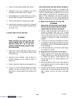
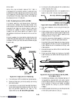
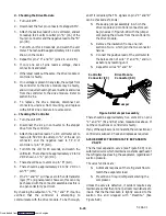
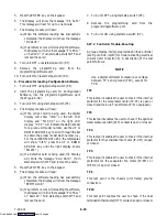
5. Using a small tube cutter, cut the liquid line just
below the moisture--line indicator. Make the cut
just below the brazed joint of the moisture--line
indicator and U--tube. Approximately, 1 inch below
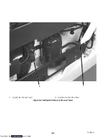
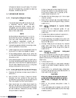
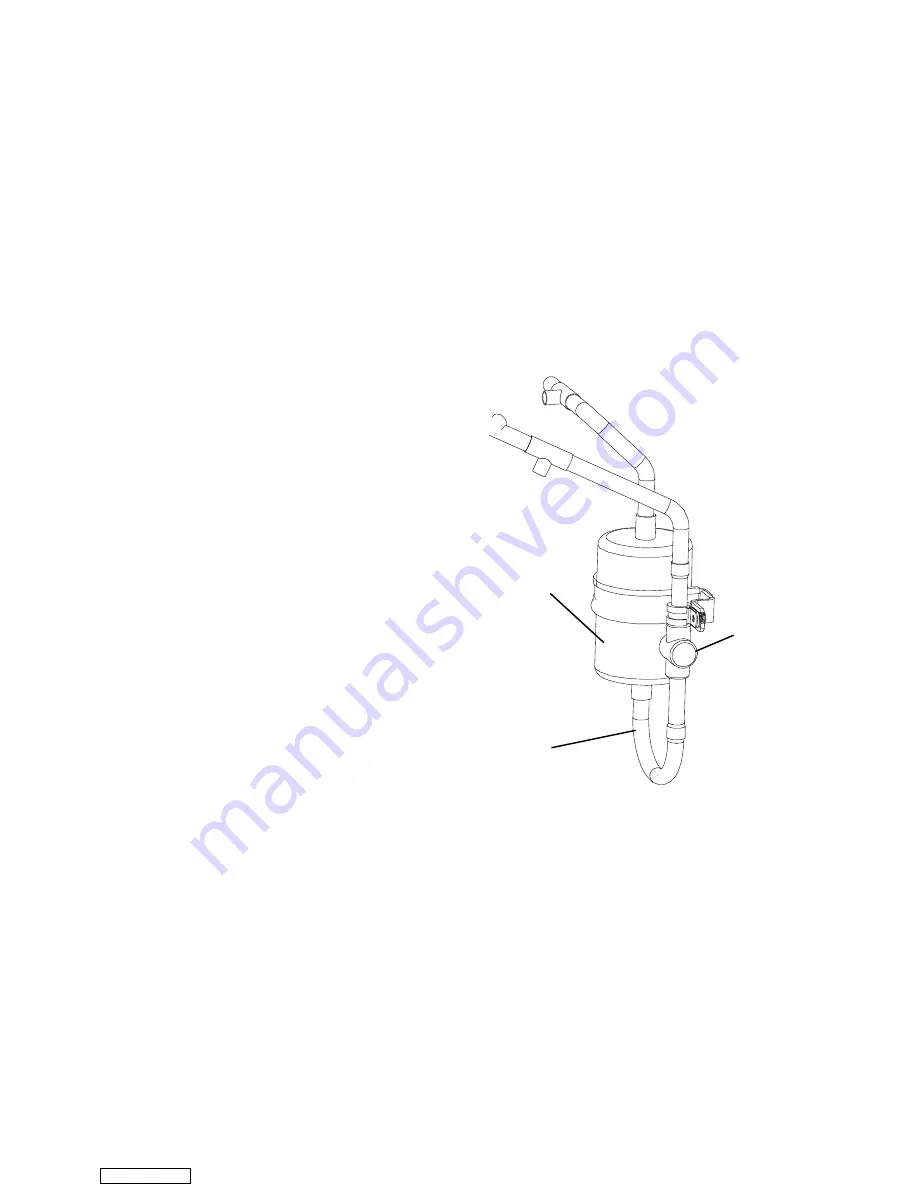
the brazed joint. Refer to Figure 6-18.
Filter Drier
Moisture-Line
Indicator
U-tube
(needs to be pierced
to remove residual oil)
Figure 6-18. Filter-Drier and U-tube
6. Using the small tube cutter, cut the U--tube just
below the filter drier, and remove the old U--tube
completely.
7. Allow oil to drain.
WARNING
Due to the nature of refrigeration systems,
there may be some residual oil. There is still
a potential for fire.
Be prepared to
extinguish the fire.
8. Braze out the filter drier and remains of the U--tube,
use kit P/N 76--50085--00 and braze in the new Filter
Drier and U--tube.
Downloaded from
Содержание 69NT40-511-200
Страница 63: ...4 3 T 294 01 Page is left intentionally blank Downloaded from ManualsNet com search engine ...
Страница 117: ...7 2 T 294 01 Figure 7 1 Electrical Schematic See Model Chart Sheet 1 of 2 Downloaded from ManualsNet com search engine ...
Страница 119: ...7 4 T 294 01 Figure 7 2 Electrical Schematic See Model Chart Sheet 1 of 2 Downloaded from ManualsNet com search engine ...

