


6-8
T-294-01
f. If the discharge pressure is more than ten psig below
the curve, add three pounds of R-134a refrigerant
through the suction line process tube.
g. Return set point to previous temperature setting.
h. The unit should be operating normally. Return to
water-cooled operation, if necessary.
i. Leave piercing valves in place for Port repair.
j. Tag the unit for Port/Maintenance repair.
9
8
7
6
5
4
4
4
3
2
1
10
11
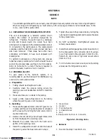
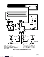
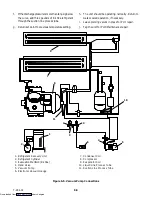
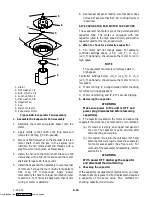
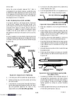
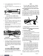
1. Refrigerant Recovery Unit
2. Refrigerant Cylinder
3. Evacuation Manifold (R-134a)
4. Hand Valve
5. Vacuum Pump
6. Electronic Vacuum Gauge
7. Condenser Coil
8. Compressor
9. Evaporator Coil
10. Liquid Line Process Tube
11. Suction Line Process Tube
Figure 6-5. Vacuum Pump Connections
Downloaded from
Содержание 69NT40-511-200
Страница 63: ...4 3 T 294 01 Page is left intentionally blank Downloaded from ManualsNet com search engine ...
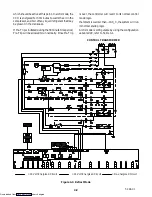
Страница 117: ...7 2 T 294 01 Figure 7 1 Electrical Schematic See Model Chart Sheet 1 of 2 Downloaded from ManualsNet com search engine ...
Страница 119: ...7 4 T 294 01 Figure 7 2 Electrical Schematic See Model Chart Sheet 1 of 2 Downloaded from ManualsNet com search engine ...


