


3-24
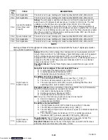
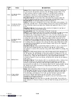
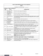
T-294-01
S
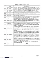
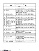
Real Time Clock (RTC) Modification
S
Pre-Trip result & data
S
Trip Start
S
ISO Trip Header (Must be entered first via
Interrogation program)
S
Economy Mode Start
S
Economy Mode End
S
“Auto 2” Pre-Trip Start
S
“Auto 2” Pre-Trip End
S
Bulb Mode Start
S
Bulb Mode changes
S
Bulb Mode End
S
USDA Trip Comment
S
CTD Controlled Atmosphere Information
S
Humidification Start
S
Humidification End
S
USDA Probe Calibration
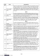
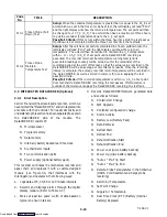
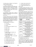
3.3.2
DataCORDER Configuration
NOTE
The DataCORDER software is integrated with
the Controller software.
Configuration to factory installed default configuration
is achieved via a common configuration card used for
controller functions, see section 3.1.2.
Changes to the factory default configuration must be
made with the Interrogation device.
Configuration:
Tells the operational software what physical
components are built into the container unit, how many
sensors to record, what recording interval should be
used, etc..
Configuration cards are available thru CTD
Replacement Components Group.
The use of a programming card in the field should only
occur under unusual circumstances, such as a physical
component in the container unit is changed to a different
component, resulting in a new configuration for the
unit.
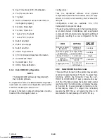
ITEM
SETTING
FACTORY
DEFAULT
Sensor Logging
(Network)
Average or
Snapshot
Average
Sensor Logging
(Thermistor)
Average, Snap-
shot or USDA
Average
Sensor Format
1 or 2 byte
1 byte
Sensor
Configuration
Refer to section
3.3.5.f.
2 sensors
Logging Interval
15, 30, 60 or
120 minutes
60 minutes
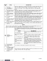
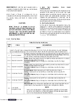
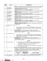
3.3.3
DataCORDER Function Codes
There are 35 functions which the operator may access to
examine the operating status of the unit. To access these
functions, perform the following: Press the ALT.
MODE & CODE SELECT keys, press an arrow key
until the left window displays the desired code number
(see Table 3-6). The right window will display the value
of this item for five seconds before returning to the
normal display mode. If a longer time is desired,
pressing the ENTER key will extend the time to 30
seconds after the last pressing of the ENTER key.
Downloaded from
Содержание 69NT40-511-200
Страница 63: ...4 3 T 294 01 Page is left intentionally blank Downloaded from ManualsNet com search engine ...
Страница 117: ...7 2 T 294 01 Figure 7 1 Electrical Schematic See Model Chart Sheet 1 of 2 Downloaded from ManualsNet com search engine ...
Страница 119: ...7 4 T 294 01 Figure 7 2 Electrical Schematic See Model Chart Sheet 1 of 2 Downloaded from ManualsNet com search engine ...


