background image


        5 

V1.0 | NRG EtherCAT User Manual | © 2022 | CARLO GAVAZZI LTD. 


EN


NRG controller 


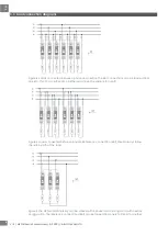
The NRG controller handles the communication with the higher-level controller and with the NRG solid 

state relays. It has to be supplied with a 24VDC supply and provides the power supply to the connected 

NRG solid state relays via the internal bus cables.  A termination resistor (RGN-TERMRES) provided with 

every NRG controller has to be fitted on the last solid state relay of the NRG bus chain. The NRG 

controller is also capable of performing internal operations to setup and maintain the internal bus. 


Various NRG Controller variants are available which facilitate communication via different 

communication protocols. These are identified via the part numbers. The  NRG controller with an 

EtherCAT communication interface is the 

NRGC-ECAT

.  


NRG solid state relays 


The RG..N solid state relays are the switching components in the NRG system. 

They are available with and without heatsink. For a reference of the variants 

available refer to the RG..N datasheet.  The RG..CM..N  utilises the 

communication system for switching, measurement and diagnostic thus 

minimising the number of components required in the system. There are 2 

variants of the RG..CM..N, the RGx1A..CM..N is the zero cross relay including 

various switching modes such as ON/OFF, Burst, Distributed full cycle and 

Advanced full cycle modes. The RGx1P..CM..N is the proportional control 

variant which on top of the aforementioned switching modes includes also 

phase angle switching and soft starting features. For more information on the 

functions of each variant refer to Section 6. 


Through the  internal BUS, the main controller can read measurement 

parameters and diagnostics information related to the RG..N and its load. The RG..N is also capable of detecting 

certain fault conditions. A fault condition is indicated through a red LED available on the façade of the RG..N. The type 

of fault can be identified through a specific flash rate of the red LED and identified via the communication system. 


Since the main controller needs to address each specific RG..N individually, each RG..N needs to be uniquely 

identifiable. It is not required to physically set the ID for each RG..N. This can be done through an auto-addressing 

function which occurs automatically on the first start up; whereby each RG..N on the bus chain will automatically be 

assigned an ID with respect to its physical placement on the internal bus. 


NRG internal cables 


The RCRGN-xxx-2 is a 5-way proprietary cable used for the internal BUS, i.e., between the NRG 

controller and the first RG..N on the BUS chain and between respective RG..Ns on the BUS. This 

internal BUS cable though terminated with a micro-USB plug is not a standard USB cable. Apart 

from the data and supply lines, the RCRGN-xxx-2 are equipped with an additional wire utilised 

for the auto-addressing of the RG..Ns on the NRG bus chain. These cables are available in 

various lengths from Carlo Gavazzi. 


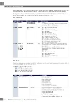
For further technical information on each NRG system component please refer to the respective product datasheets: 


System 

component 

Datasheet 

QR Codes 

NRGC-ECAT 

http://gavazziautomation.com/docs/mt_gh/SSR_NRGC_ECAT.pdf


RG..CM..N  


http://gavazziautomation.com/docs/mt_gh/SSR_RG_CM_N.pdf


RCRGN-xxx-2 

http://gavazziautomation.com/docs/mt_gh/SSR_RG_CM_N.pdf


Содержание NRG EtherCAT

Страница 1: ...NRG EtherCAT User Manual Operating instructions Manuale d istruzioni Betriebsanleitung Manuel d instructions Manual de instrucciones Brugervejledning...

Страница 2: ...ounding 10 4 EtherCAT Configuration 11 4 1 Installing the ESI file in TwinCAT 11 4 2 Integrating the NRG in TwinCAT 11 4 3 Configuration of the NRG bus chain in TwinCAT 13 4 4 Start up Parameters 14 5...

Страница 3: ...equipment Nor can Carlo Gavazzi assume liability for recommendations that appear or are implied in the following description The information in this document is not considered binding on any product w...

Страница 4: ...e related national legislation please note that WEEE cannot be disposed of as municipal waste and such waste must be collected and disposed of separately the public or private waste collection systems...

Страница 5: ...more solid state relays are needed in a system multiple BUS chains can be utilised Each BUS chain connects to another BUS chain in a line topology via the NRG controllers of the respective BUS chains...

Страница 6: ...ation on the functions of each variant refer to Section 6 Through the internal BUS the main controller can read measurement parameters and diagnostics information related to the RG N and its load The...

Страница 7: ...the main controller via the 2xRJ45 shielded communication ports The connection between the NRG controller and the solid state relays is through the internal bus cables Each RG N is equipped with 2x mi...

Страница 8: ...ny network topology If more than 32 solid state relays are required in an application multiple bus chains can be utilised These can be configured in a line or star topology as deemed fit for the appli...

Страница 9: ...tions can be looped from one RG CM N to another since all the loads have the same return path Figure 5 Loads connected between phases Reference connection Ref should always follow the return path of t...

Страница 10: ...on on the bus In case of an RG N replacement or any changes to the NRG bus chain the RG Ns have to be re addressed Follow the procedure below Figure 8 to re address the RG Ns on the NRG bus chain manu...

Страница 11: ...il must be conductive and grounded Shielded Cat 5e cables fitted with an outer metallic shell should be used The shell should be connected to the wire screen of the cable Figure 9 Metal din clip on NR...

Страница 12: ...file from https gavazziautomation com images PIM OTHERSTUFF ESI ESI_NRGC ECAT zip and relocate it in the TwinCAT default directory C TwinCAT 3 1 Config Io EtherCAT 4 2 Integrating the NRG in TwinCAT L...

Страница 13: ...LO GAVAZZI LTD V1 0 NRG EtherCAT User Manual 2022 CARLO GAVAZZI LTD EN Find the NRGC ECAT in the EtherCAT device list under Carlo Gavazzi Ltd NRG Controller with EtherCAT Figure 13 Find the NRGC ECAT...

Страница 14: ...maximum of 32 RG N solid state relays can be connected to 1 NRGC ECAT In the Slots tab populate the modules depending on which variant of the RG N solid state relays will be installed in the relevant...

Страница 15: ...meters can be assigned or re assigned via a service data object Check Communications section for further information If start up parameters are left blank the values saved internally in the RG Ns will...

Страница 16: ...mit are mutually exclusive 0 255 0 25 5s Default 0s OFF time to soft start only for RGx1P N 0x2xx2 02 Set the non firing time before soft start is reactivated 0 soft start with occur on power up only...

Страница 17: ...voltage used to compensate for deviations in voltage when Voltage Compensation is activated 0 Voltage compensation is disabled 42 600 V reference voltage for voltage compensation 0 42 600V Default 0...

Страница 18: ...t 0 Mains loss alarm Flag Bit 1 Load loss SSR open circuit alarm Flag Bit 2 RG N short circuit alarm Flag Bit 3 Voltage out of range alarm Flag Bit 4 Current out of range alarm Flag Bit 5 Frequency ou...

Страница 19: ...ble error Flag Bits 12 15 Not used shall be 0 0xF100 0xF100 xx xx RG N position on bus chain in hex Device Status 1 byte Bit 0 Substitute submodule Module type does not match installed RG N variant co...

Страница 20: ...eps of 0 01 therefore a value of 1745 17 45A Check Measurements section for more information 0 RG N model dependent UCL value Default RG N model dependent Under current limit UCL 0x2xx1 05 0 RG N mode...

Страница 21: ...6 Set the firing mode that the RG N shall use at the output 0 External only for RGx1A N 1 ON OFF 2 Burst 3 Advanced full cycle 4 Distributed full cycle 5 Phase Angle only for RGx1P N RGx1A N default O...

Страница 22: ...eading 0 default SSR ON time read only 0x2xx6 03 Holds the accumulated time in hours that the output of the RG N was switched ON 0 default Control level feedback only for RGx1P N read only 0x2xx7 01 H...

Страница 23: ...tput OFF and a control level of 100 indicates SSR output ON The advantages of this mode are It is effectively a direct replacement of the A1 A2 i e for existing systems the control algorithm within th...

Страница 24: ...ing mode 33 control level Output with Distributed firing mode 50 control level Output with Distributed firing mode 66 control level The advantage of Distributed over Burst is the reduction in thermal...

Страница 25: ...d heater applications AFC has the disadvantage of worse harmonics emissions than Burst and also slightly worse than Distributed Phase Angle Firing mode The Phase angle switching mode is available only...

Страница 26: ...e mode The soft start will apply the power smoothly to the load over a time period of maximum 25 5s This is settable via the communication system Soft start ramping time setting Soft start with curren...

Страница 27: ...ue of 50 means 0 5A and a value of 1747 means 17 47A If a fault occurs in the system such that it is not possible to measure the current this value is 0 This reading is updated every half cycle but is...

Страница 28: ...m the initial value at power up the running hours during this power up The reading is updated in steps of 1hour hence a value of 1034 would mean 1034h that the output was ON during its lifetime In the...

Страница 29: ...lickering Invalid configuration General Configuration error Possible reason State change commanded by master is impossible due to register or object settings Double Flash Application watchdog timeout...

Страница 30: ...rror Description This alarm is issued if the NRG controller detects that the BUS between the NRG controller and the RG Ns is not correctly terminated This can be due to An internal fault in the NRG co...

Страница 31: ...Iref registers will be updated by measuring the present current and voltage over a period of time The TEACH command is refuted in case of alarms present on the system If the TEACH is unsuccessful the...

Страница 32: ...sued if this condition is present for 10 seconds Though indicated as an alarm condition this alarm has no effect on the function on the RG N and it is up to the user to decide what to do when this ala...

Страница 33: ...ceived by the RG N and or replies will not be correctly received by the NRGC and or main controller Diagnose Confirm presence of 24V supply voltage on the NRG Controller US terminals Otherwise replace...

Страница 34: ...k it is important to turn it off by pressing again the blue button 2 5 secs otherwise PLC cannot communicate with the NRG bus chain 8 2 Replacing an RG N When an RG N has to be replaced 1 Connect the...

Страница 35: ...REF terminal however this will constitute some limitations as listed below 1 The following readings are not available RMS Voltage Real Power and Apparent Power 2 The TEACH operation cannot be executed...

Отзывы: