


31
V1.0 | NRG EtherCAT User Manual | © 2022 | CARLO GAVAZZI LTD.
EN
Diagnose
Make sure that load is not faulty or if the SSR is in an open circuit condition. If an
RG..N is replaced, make sure to follow the re-addressing procedure.
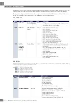
SSR Short Circuit
Description
This condition is identified when current >300mA flows through the RG..N output
when control signal is OFF.
Diagnose
Make sure that the appropriate short circuit protection is utilised. If an RG..N is
replaced, follow readdressing procedure at power-up. Check load and protection
devices (fuses or Miniature Circuit Breakers) status before re-starting.
Frequency out of range
Description
This condition is identified when the frequency measured by the RG..N is not within
the set range hence is > Over Frequency value or < Under Frequency value. This
alarm is issued if this condition is present for >10 seconds. Though indicated as an
alarm condition, this alarm has no effect on the function on the RG..N and it is up
to the user to decide what to do when this alarm is activated.
Diagnose
Check line frequency and ensure that the over and under frequency limits are set
properly. Though the switching function of the RG…N is not affected by this alarm,
care must be taken to make sure RG..N is operated within its rated specification.
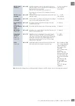
Current out of range
Description
This condition is identified when the current measured by the RG..N is not within the
set range hence is > Over Current value or < Under Current value. This alarm is
issued if this condition is present for >10 seconds. Though indicated as an alarm
condition, this alarm has no effect on the function on the RG..N and it is up to the
user to decide what to do when this alarm is activated.
The over current limit is bounded by the maximum current for each NRG solid state
relay variant. A list of the variants with their maximum current values is listed in the
table below.
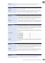
Current limits
RGC1A60CM25KEN
33
RGC1A60CM32KEN
33
RGC1A60CM32GEN
47
RGC1A60CM42GEN
64
RGC1A60CM62GEN
93
RGS1A60CM50KEN
55
RGS1A60CM92KEN
99
RGS1A60CM92GEN
99
Diagnose
The over current limit is bounded by the maximum current for each NRG solid state
relay variant. A list of the variants with their maximum current values is listed in the
table above.
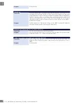
Voltage out of range
Description
This condition is identified when the voltage measured by the RG..N is not within
the set range hence is > Over Voltage value or < Under Voltage value. This alarm
is issued if this condition is present for >10 seconds. Though indicated as an alarm
condition, this alarm has no effect on the function on the RG..N and it is up to the
user to decide what to do when this alarm is activated.
Diagnose
Check mains and ensure that the over and under voltage limits are set properly.
Though the switching function of the RG…N is not affected by this alarm, care must
be taken to make sure RG..N is operated within its rated specification.
Communication (BUS) error
Description
This alarm indicates that there is a communication problem between the NRGC-
ECAT and the RG..N. It is only issued via the Alarm LED on the RG..N. This alarm
should also trigger the BUS error alarm via the communication system.


