17
V1.0 | NRG EtherCAT User Manual | © 2022 | CARLO GAVAZZI LTD.
EN
5.
Communication
5.1
Process data (PDO)
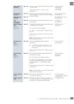
Process data is the transmission of real time data between an EtherCAT slave and an EtherCAT controller. In the NRG
system, process data is exchanged between the EtherCAT Controller and the RG..N solid state relays. The data
includes parameters and diagnostics measured by each NRG solid state relay as well as the control level from the
PLC to control each solid state relay. Values are stored in a big endian format.
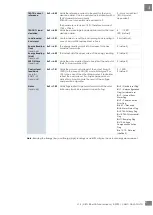
TxPDO - Input Process Data
Data
Data type
Status
uint16
Alarm
uint16
Voltage RMS Reading
uint16
Hold Current Reading
uint16
Current RMS Reading
uint16
Real Power Reading
uint16
The current measurements (Current RMS & Hold Current) is returned as scaled integers. Therefore, a current value of
16.81A will be received as 1681. The PLC program has to convert the numbers into floating point values. For further
information regarding the scaling of each measurement, refer to the Measurements section in this User Manual.
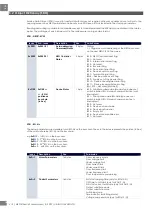
The bits in the Alarms and Status WORDs represent alarms and status flags present on the respective solid state relay.
Name
Description
Alarms
Bit 0 – Mains loss alarm Flag
Bit 1 – Load loss/SSR open circuit alarm Flag
Bit 2 – RG..N short circuit alarm Flag
Bit 3 – Voltage out of range alarm Flag
Bit 4 – Current out of range alarm Flag
Bit 5 – Frequency out of range alarm Flag
Bit 6 – Over-temperature pre warning alarm Flag
Bit 7 – Temperature out of range alarm Flag
Bit 8 – Load deviation alarm Flag
Bit 9 – Soft start current limit reached Flag
Bit 10 – Voltage compensation not possible Flag
Bits 11:15 - Not used.
(shall be 0)
Status
Bit 0 – Device reset Flag
Bit 1 – Autoconfiguration Flag (for internal use)
Bit 2 – Internal Error Alarm Flag
Bit 3 – Communication Error Flag
Bits 4:7 – Not used
Bit 8: Alarm Status Flag
Bit 9: TEACH busy Flag
Bit 10: TEACH successful Flag
Bit 11: Ramping Flag
Bit 12: Voltage Compensation Active Flag
Bits 13:15 - Not used.
(shall be 0)
Note
: ‘Ref’ terminal connection is required for Voltage, Apparent Power and Real Power readings. Otherwise, the
readings of these parameters will be 0.
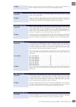
RxPDO – Output Process Data
Data
Data type
Control level (0 -100%)
uint8
In case of
ON/OFF
control mode, a control level
< 100%
shall indicate SSR output
OFF
and a control level of
100%
shall
indicate SSR output
ON
.
For the
Power control
firing modes (Burst, Distributed full cycle, Advanced full cycle and Phase Angle) the
% control
value
shall be translate to
% power
of the SSR output. Refer to Section 6.2 for more information on Switching Modes.

