


100
Specifications are subject to change without notice. Pictures are just an example. For special features and/or customization, please ask to our sales network. 07/18
CERTUS Installation Manual
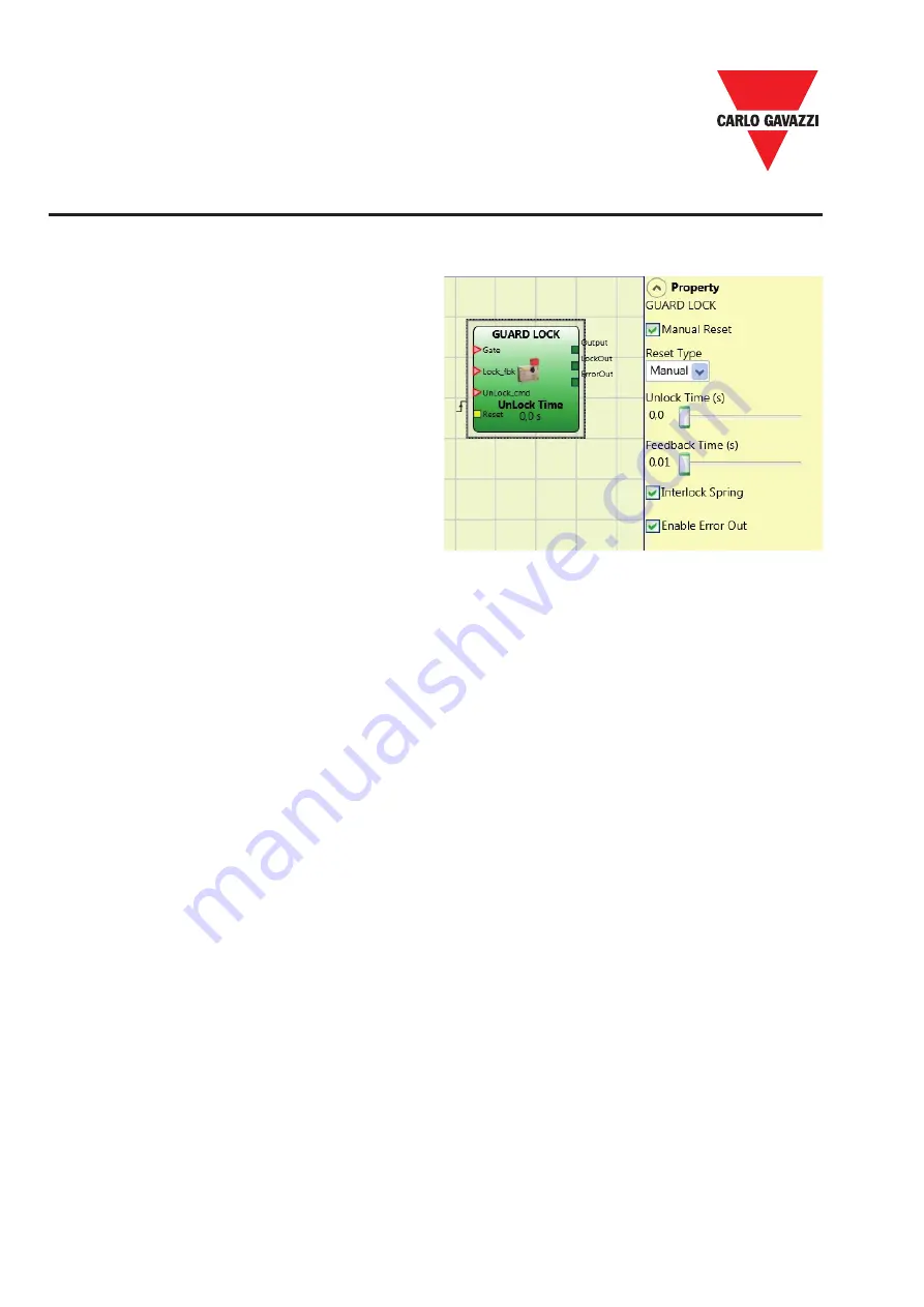
Guard Lock
Guard Lock Operatos
The GUARD LOCK operator controls locking/
unlocking of an
ELECTROMECHANICAL
GUARD LOCK
by analysing consistency
between the Lock command and the status
of an E-GATE and a FEEDBACK. The main
ouput is 1 (TRUE) when the guard lock is
closed and locked.
Operating principles.
The function acts as a gate safety lock.
1) The GATE input must always be connected to an E_GATE lock input (guard feedback).
2) The Lock_fbk input must always be connected to a LOCK FEEDBACK (feedback coil lock)
input element.
3) The UnLock_cmd input can be connected freely in the diagram and determines the
request to unlock (when in LL1 state).
4) The OUTPUT signal of this element is 1 (TRUE) if the guard is closed and locked. When
an unlock command is applied to the UnLock_cmd input, the OUTPUT signal is set to “0”
and the guard is unlocked (LockOut output) after a time UnLock_Time configurable as
parameter. This output goes to 0 (FALSE) even when error conditions are present (eg.
open door with lock locked, Feedback Time that exceeds the maximum allowed, ...).
5) Lockout signal controls the locking/unlocking of the guard.
Parameters
Unlock Time (s):
The time that must pass between the UnLock_cmd input reaching and the real guard unlock
(Lockout output).
0 ms ÷ 1 s Step 100 ms
1.5 s ÷ 10 s Step 0.5 s
15 s ÷ 25 s Step 5 s
Feedback Time (s):
Maximum delay accepted between LockOut output and Lock_fbk input (must be the one
shown on the lock data sheet with appropriate gap decided by the operator).
10 ms ÷ 100 s Step 10 ms
150 ms ÷ 1 s Step 50 ms
1.5 s ÷ 3 s Step 0.5 s
Interlock Spring:
The guard is locked passively and released actively, i.e. the mechanical
force of the spring keeps it locked. The guard thus continues to be locked even when the
power supply is disconnected.


