


Model G3B Gas burner — Instruction manual
MNG3B Gas 041015
19
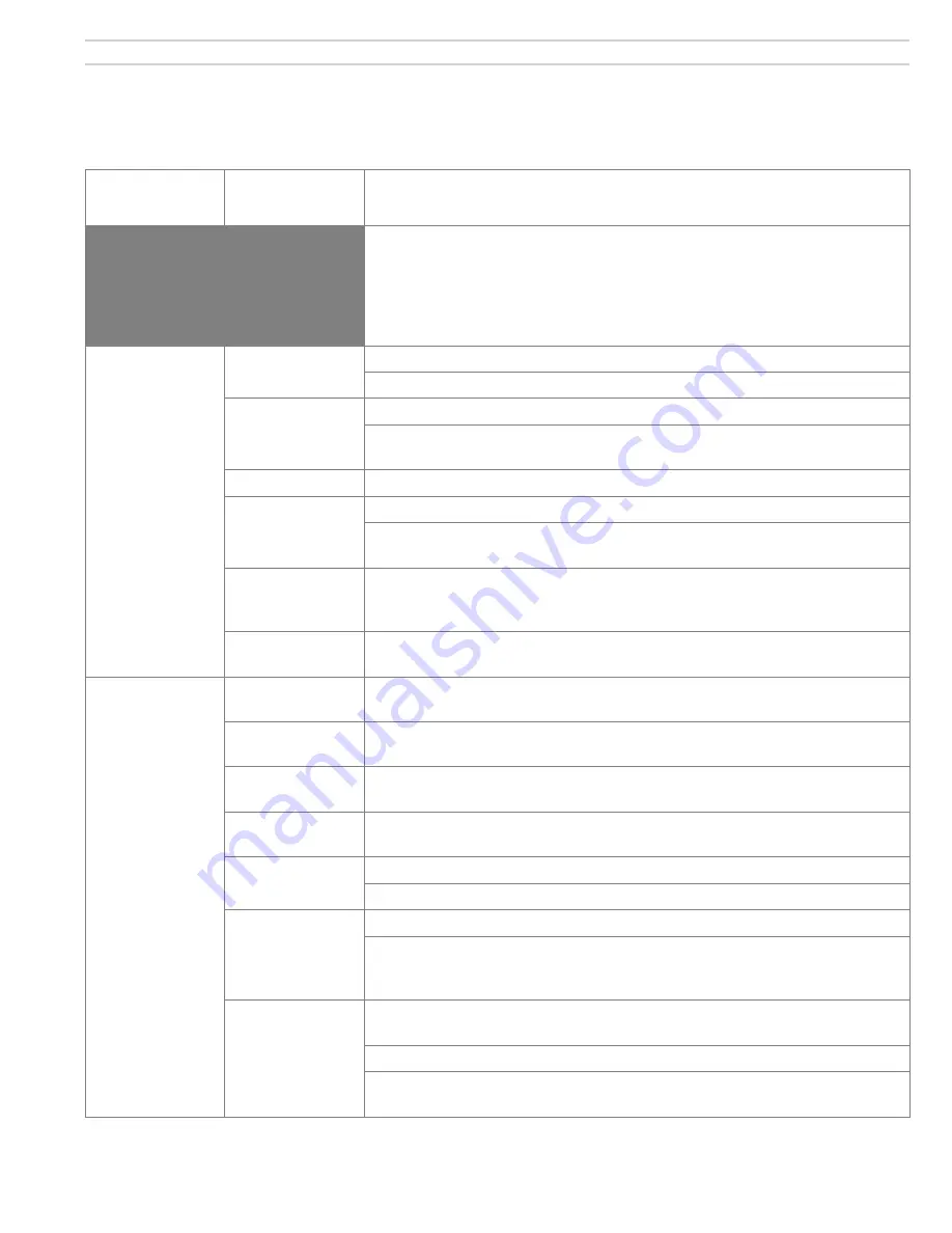
7. Troubleshooting
Problem
Possible
cause
Corrective action
WARNING
These procedures must only be performed by a qualified service
technician. Use care when performing tests on electrically or
mechanically live parts. Disconnect power to burner/appliance and close
main manual gas valve when removing components for service. Failure
to comply could result in severe personal injury, death or substantial
property damage.
Burner motor will
not start
120 V power
Check 120 V at terminal strip. L1 - L2
Check limit/operative circuit.
24 V circuit
Check that 24 V thermostat/circuit is calling for heat.
Check transformer output. Each “T” on terminal strip should read
approx. 24 volts to “G” ground.
Incorrect wiring
Check all field and factory wiring.
Bad motor relay
Check 24 V at motor relay. Relay should click (pull-in) on call for heat.
Check continuity across contacts (N.O.) or each side of contact to L2 on
terminal strip should read 120 volts.
Bad motor
If motor relay is good (see above) and wiring is correct, disconnect the
motor leads and power the motor directly with 120 V to check motor
operation.
Bad primary
control
If all above tests prove negative replace control.
Burner pre-
purges for 34
seconds but
does not light
(continued on
next page)
Incorrect air
setting
For initial light-off set air throttle according to desired input.
Wrong orifice
size
Check orifice drill size.
Manual gas shut-
off valve closed
Check supply line gas cock and manual shut-off valve on combination
gas valve.
Manifold
pressure
Adjust regulator to 3.5 W.C. for natural gas and propane.
Gas valve not
opening
Check for 24 V valve coil during TFI. Indicator light should also be on.
Line pressure in excess of 14.0 W.C. can damage valve.
Motor end switch
not making
Check motor end switch.
Disconnect the two red leads in the panel coming from the motor end
bell. Check continuity during pre-purge. End switch will not activate if
motor is not running up to speed.
Hot surface
ignition element
damaged
Element normally glows red within 20 seconds during pre-purge. Use
flame mirror to visually inspect.
Check for 120 V at rear of ignitor assembly during pre-purge.
If visual inspection cannot be done, remove element and power directly
with 120 V. Replace element if it does not glow red within 45 seconds.