ENG
“Power+” +0300050EN - rel. 2.3 - 08.06.2012
11
Note
: the control signals terminal unit 1...8 and the relay terminals unit
9, 10 are double isolated from each other and with respect to the power
terminal board.
Important
:
•
in the European Union, all units that incorporate the drive must comply
with the Machinery Directive 2006/42/EC. Specifi cally, the manufacturer
of the unit is responsible for the installation of a main switch and the
conformity to standard EN 60204-1;
•
for fi xed installations according to IEC61800-5-1, a disconnect device is
required on the circuit between the power supply and the drive;
•
only use permanently wired power input connections; the drive must be
earthed: the earth wire must be sized for the maximum fault current that is
normally limited by the fuses or a circuit breaker.
3.7 Conformity to EMC standards
Power+ is designed in compliance with the high EMC standards. All models
are supplied with an internal EMC fi lter, designed to reduce the emissions
taken towards the power supply line in conformity with harmonised European
Standards. It is the installer’s responsibility that the device or system within
which Power+ is incorporated is in compliance with the Standards in force
in the country of use. The Standard in force within the European Union is the
EMC 2004/108/EC Directive. Power+ is intended to be incorporated inside
fi xed installation devices, only installed by specialised staff .
Conformity with the EMC Standard means that the indications given in the
“Electric connections” paragraph are respected and, as it also depends on
wiring topology, it must be checked on the fi nal machine as envisioned by
the Final Product Standard.
3.8 Electrical
connections
For installation proceed as shown below, with reference to the general
connection diagram (par. 3.10).
Important
:
the following warnings must be observed when connecting the drive:
•
separate as much as possible the probe and digital input cables (at least 40
cm) from the power cables to avoid possible electromagnetic disturbance.
Never lay power cables (including the electrical panel cables) and probe
signal cables in the same conduits;
•
the cables must be sized according to the table in paragraph 9.1;
•
when the fuses are used, these must be chosen according to the data
shown in the table in paragraph 9.1, and must comply with the national
and local standards in force. In general, use type gG fuses for IEC and type
T for UL, with a blow time less than 0.5 s;
•
when a magnetic circuit breaker (MCB) is used, it must be of type B, rated
according to the data shown in the table in paragraph 9.1;
•
avoid installing cables connected to the control terminal block in the
immediate vicinity of power devices (contactors, circuit breakers, etc.).
Reduce the path of the cables as much as possible, and avoid spiral paths
that enclose power devices.
Use cables rated to 90 °C, and if the temperature of the terminals exceeds 85
°C, use cables rated to 105 °C. Use cable terminals suitable for the terminals
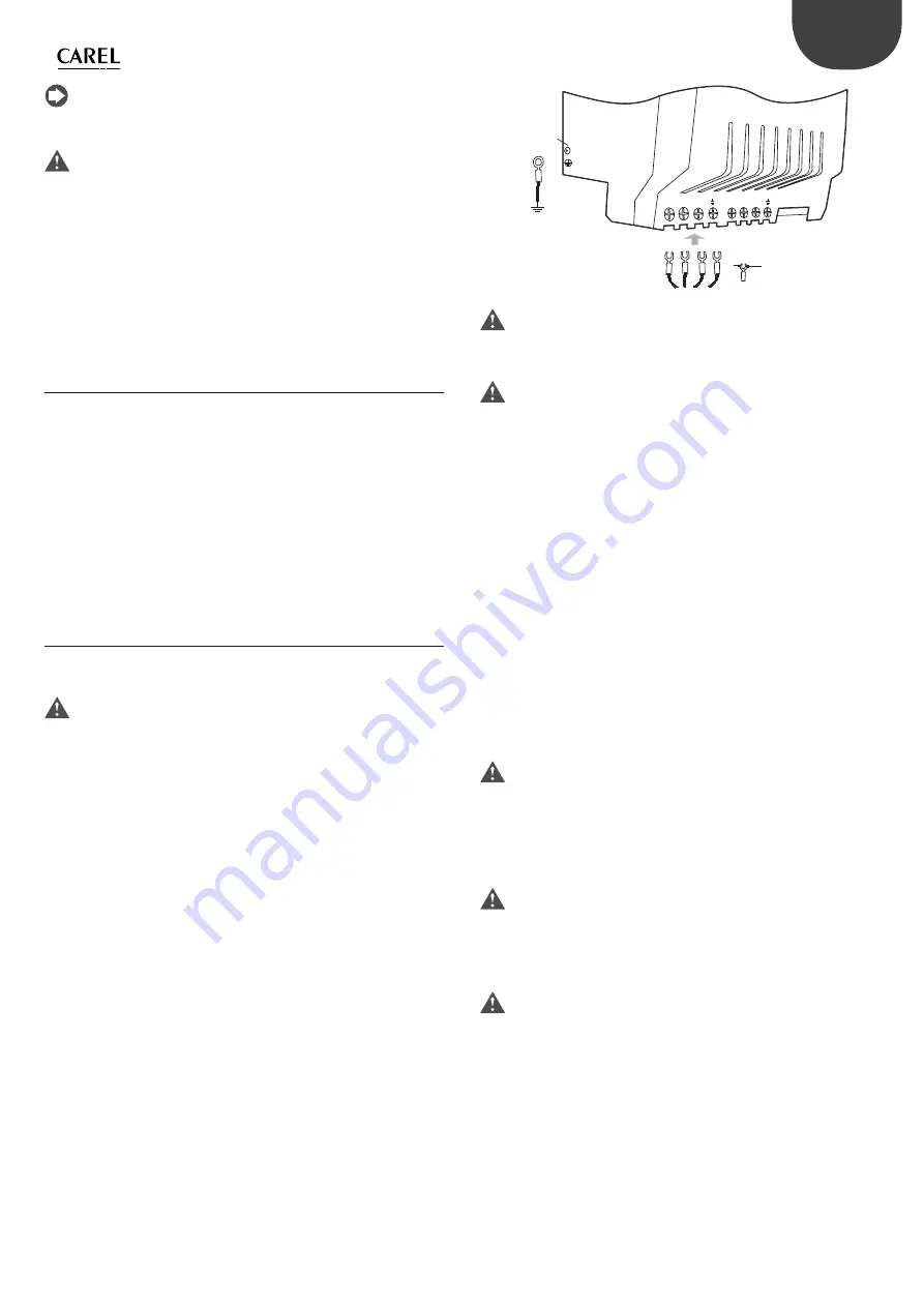
and the cables used. Loosen each screw and insert the cable ends, then
tighten the screws and lightly tug the cables to check correct tightness. For
fork cable terminals, do not exceed the maximum width shown in the fi gure.
L1/L L2/N L3
U
V
W
Vite / screw
M4
7,5 mm MAX
Fig. 3.h
Important
: the tightening torque is:
•
power terminals: 1 Nm;
•
control terminals: 0,5 Nm.
Important:
In the unscrewing phase, do not force the screw further when it is fully
home.
The drive must be earthed: to do this, use either the screw terminal (earth
symbol ), or the screw (PE symbol ) on the side of the heat sink, in accordance
with local standards in force. To minimise EMC problems, use a power cable
with earth wire included, connected to terminal . The power supply earth
must be connected directly to the earth bar in the electrical panel, without
branches to other devices; the earth wire size must be greater than or equal
to the phase wires; the earth impedance must be compliant with national
and local standards; in compliance with UL requirements, the protective
earth connections (PE) must be made using eyelet lugs. On single-phase
models, also connect the PFC coil. On three-phase models, where necessary
connect the optional DC choke in place of the jumper that closes terminals
C1 and C2. See the “Terminals C1 and C2” paragraph.
P
ower supply
Connect the power cables: for single-phase models connect the power
supply to terminals L1/L and L2/N, for three-phase models to terminals L1, L2,
L3; for the size of the cables and the type of fuses, see the table in paragraph
9.1.
Important
:
•
do not connect the power supply to terminals U, V, W;
•
make sure the voltage, frequency and number of phases in the power
supply match the ratings of the specifi c model.
Terminals
C1
and
C2
Important:
The use of terminals C1 and C2 depends on the model and diff ers based on
the type of power supply: single-phase or three-phase.
Models with 200/240 Vac single-phase power supply
Connect the PFC coil supplied with the drive to terminals C1 and C2.
Important
:
Never short-circuit terminals C1 and C2.
The PFC coil does not require connection to earth.
See paragraph 3.12 for dimensions of the PFC coil.
Содержание Power+
Страница 2: ......
Страница 4: ......
Страница 6: ...ENG Power 0300050EN rel 2 3 08 06 2012 6 ...
Страница 35: ......


