17
ENG
"humiFog direct" +0300073EN rel. 1.0 - 31.03.2017
Important
: unlike the first zone, the connection to the c.pCOe expansion
relating to the second zone can supply power to probes that require up
to 21 Vdc.
4.4 Analogue signal from an external
controller
As an alternative to the main probe, a signal from an external controller
can be used. The latter processes the request to send to humiFog Direct
via an analogue signal, which varies from 0 to 100%. humiFog will adjust
the capacity delivered proportionally to the signal received, and the
display will show the request sent as a percentage.
The following types of proportional signals are allowed:
•
4-20 mA, 0-20 mA current signals
•
0-10 V, 0-1 V, 2-10 V voltage signals
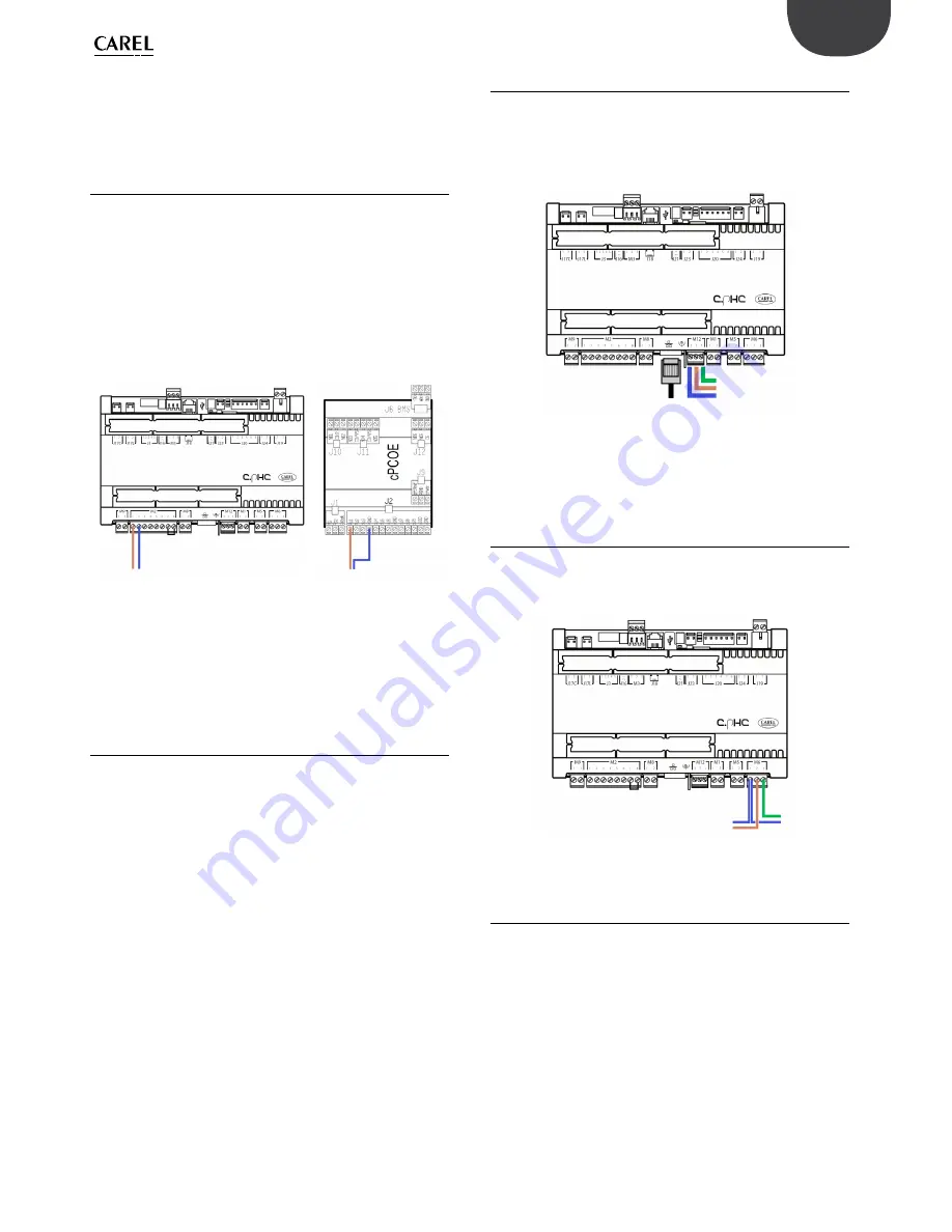
The external signal for the first zone is connected to the c.pHC controller
via inputs 1 [IN a] and 2 [GND] on terminal M2.
The external signal for the second zone is connected to the c.pCOe
controller via inputs U1 [IN a] and [GND] on the terminal J2.
Fig. 4.e
Fig. 4.f
The limit probes can also be associated with the external proportional
signal, and will be connected as shown in the previous paragraphs.
4.5 Digital signal from humidistat or
external controller
The signal from the external controller can be replaced by the signal from
a humidistat, thermostat, or any external device with digital contact. In
this case, humiFog Direct will work in ON/OFF mode, either delivering
100% of flow-rate or remaining in standby. The capacity delivered can be
reduced by setting parameter P0 (the reduction is managed by PWM, see
paragraph 6.5).
The electrical connection is the same as in the previous case shown in
Figure 4.D. Make sure to configure the humiFog Direct (via the screens
on the display) so that it can be controlled by an ON/OFF signal from
external controller or device.
4.6 Serial or Ethernet communication
humiFog Direct can be controlled by a supervisor that reads the humiFog
Direct parameters and sends commands. To connect a supervisor, the
RS485 serial port (terminal M12, inputs 1 [Tx/Rx-] 2 [Tx/Rx+] 3 [GND]) or
Ethernet port is used. The choice of which port to use depends on the
supervisor. Modbus and BACnet communication protocols are available
as standard: no auxiliary cards need to be fitted on the c.pHC controller
Fig. 4.g
The Ethernet port can also be used for the Webserver function (see
Chapter 8), so as to monitor and control humiFog Direct via a local
network, without needing a supervisor.
4.7 Alarm relay output
The digital output for communication of an alarm status is connected to
contacts 1-2-3 on terminal M6 on the c.pHC. N.C. logic is set by connecting
the two wires to contacts 1-2, while N.O. logic is set connecting the two
wires to contacts 1-3.
Fig. 4.h
4.8 Unit status digital output
The c.pHC controller provides a digital output corresponding to
unit status. This is a voltage-free contact that provides the following
information:
•
contact closed: unit on or in standby
•
contact open: unit off (OFF from keypad or from remote contact, or
no power)
The unit status digital output is available at contacts 1-2 on terminal M5
on the c.pHC.
[IN a] [GND]
[IN a] [GND]
EXTERNAL SIGNAL ZONE 1
EXTERNAL
SIGNAL ZONE 2
1 [Tx/Rx-]
2 [Tx/Rx+]
3 [GND]
SERIAL RS485
ETHERNET
N.C.
N.O.
ALARM RELAY
Содержание humiFog direct
Страница 2: ......
Страница 4: ...4 ENG humiFog direct 0300073EN rel 1 0 31 03 2017...
Страница 6: ...6 ENG humiFog direct 0300073EN rel 1 0 31 03 2017...
Страница 38: ...38 ENG humiFog direct 0300073EN rel 1 0 31 03 2017 12 APPENDIX 12 1 Single zone cabinet wiring diagram Fig 12 a...
Страница 39: ...39 ENG humiFog direct 0300073EN rel 1 0 31 03 2017 12 2 Two zone cabinet wiring diagram Fig 12 b...
Страница 43: ......


