


26
ENG
“EVD evolution” +030222041 - rel. 1.0 - 01.06.2008
t
t
t
t
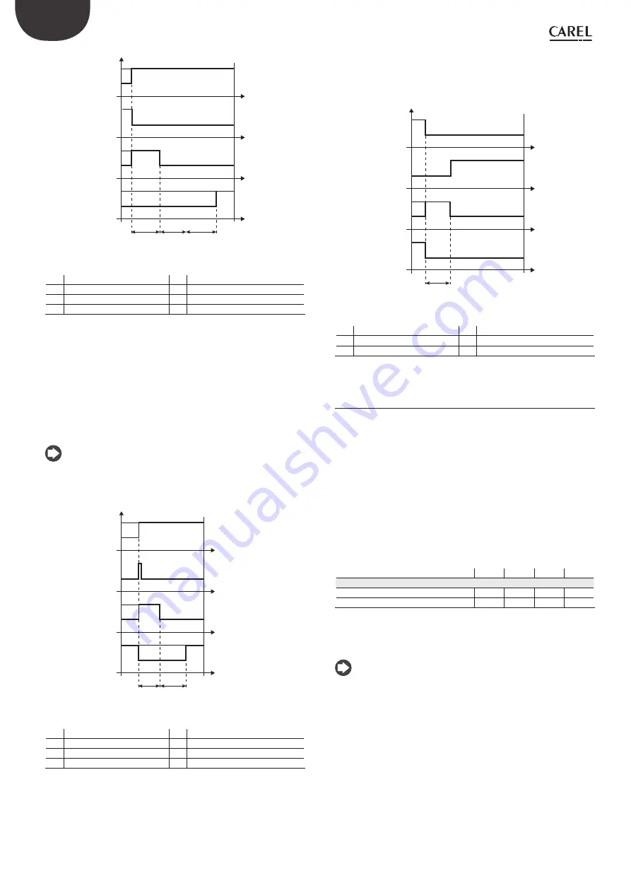
OFF
ON
R
OFF
ON
P
OFF
ON
S
OFF
ON
A
T1
T2
W
Fig. 6.b
Key:
A
Control request
W
Wait
S
Standby
T1
Pre-positioning time
P
Pre-positioning
T2
Start delay after defrost
R
Control
t
Time
Positioning (change cooling capacity)
This control status is only valid for the pLAN driver.
If there is a change in unit cooling capacity of at least 10%, sent from the
pCO via the pLAN, the valve is positioned proportionally. In practice, this
involves repositioning starting from the current position in proportion to
how much the cooling capacity of the unit has increased or decreased
in percentage terms. When the calculated position has been reached,
regardless of the time taken (this varies according to the type of valve
and the position), there is a constant 5 second delay before the actual
control phase starts.
Note:
if information is not available on the variation in unit cooling
capacity, this will always be considered as operating at 100% and therefore
the procedure will never be used. In this case, the PID control must be
more reactive (see the chapter on Control) so as to react promptly to
variations in load that are not communicated to the driver.
t
t
t
t
OFF
ON
R
OFF
ON
NP
OFF
ON
C
OFF
ON
A
T3
W
Fig. 6.c
Key:
A
Control request
T3
Repositioning time
C
Change capacity
W
Wait
NP Repositioning
t
Time
R
Control
Stop/end control
The stop procedure involves closing the valve from the current position
until reaching 0 steps, plus a further number of steps so as to guarantee
complete closing. Following the stop phase, the valve returns to
standby.
t
t
t
t
OFF
ON
R
OFF
ON
ST
OFF
ON
S
OFF
ON
A
T4
Fig. 6.d
Key:
A
Control request
R
Control
S
Standby
T4
Stop position time
ST
Stop
t
Time
Special control status
6.3
As well as normal control status, the driver can have 3 special types of status
related to specific functions:
manual positioning:
•
this is used to interrupt control so as to move the
valve, setting the desired position;
recover physical valve position:
•
recover physical valve steps when
fully opened or closed;
unblock valve:
•
forced valve movement if the driver considers it to be
blocked.
Manual positioning
Manual positioning can be activated at any time during the standby or
control phase. Manual positioning, once enabled, is used to freely set the
position of the valve using the corresponding parameter.
Parameter/description
Def.
Min.
Max.
UOM
Control
Enable manual valve positioning
0
0
1
-
Manual valve position
0
0
9999
step
Tab. 6.k
Control is placed on hold, all the system and control alarms are enabled,
however neither control nor the protectors can be activated. Manual positio-
ning thus has priority over any status/protection of the driver.
Note:
the manual positioning status is NOT saved when restarting after a
•
power failure.
in for any reason the valve needs to be kept stationary after a power
•
failure, proceed as follows:
remove the valve stator;
-
in Manufacturer programming mode, under the configuration
-
parameters, set the PID proportional gain= 0. The valve will remain
stopped at the initial opening position, set by corresponding
parameter.


