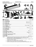
Carefree of Colorado
Installation Manual
Mirage
3
052979-003r5
I
NSTALLATION
I
T IS RECOMMENDED THAT THREE PEOPLE INSTALL THE AWNING DUE TO THE SIZE AND WEIGHT OF THE COMPONENTS
!
R
EQUIRED
P
RE
-I
NSTALLATION
P
ARAMETERS
Prior to installing the awning, the installer must determine the layout of the specific construction elements to
successfully assemble and mount the awning.
1. Determine the location, size and type of structural framing in the area where the awning is to be mounted.
There must be structural framing at the awning mount locations. Fiberglass or sheet metal siding
alone is
NOT
strong enough to support the weight of the awning!
If the framing is not obvious, it may be possible to use a stud finder or other similar device to locate
the frame.
If in doubt, contact the coach manufacturer to determine the type and position of the structural frame.
2. Determine the mounting locations for the control box and switch assemblies.
For 110VAC installations, the installer must provide enclosed junction boxes for all wire splices. Boxes are
required in conformance with prevailing construction codes.
At the control box location, AC input is required. It is recommended that the installer provide a
dedicated AC circuit for the awning system that is protected by an appropriate sized fuse/circuit
breaker. Each patio awning draws a maximum of 3 amps.
M
OUNTING
P
LATE
L
AYOUT AND
I
NSTALLATION
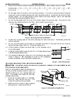
1. Determine the location of the awning:
Mounting area must be plumb and clear of obstacles;
The mounting plate is 9" shorter than the awning (w/ standard end caps); 6" shorter than the back plate.
(Reference Figure 1)
The awning is factory set with minimum pitch. Mounting height above a door opening or slide-out room
must be adjusted for a greater pitch. The chart below provides the minimum distance from the top of a
protrusion to the bottom of the mounting plate when the awning is set at
MINIMUM
and
MAXIMUM
pitch:
Bottom
of Case
Maximum Height of Projection
A
B
Travel Path
10"
119"
Maximum
Pitch
Minimum
Pitch
mirage008b
Bottom
of Case
35"
114"
Minimum Height (B) is measured from the uppermost edge of the projection
(i.e. door, slide-out room flange) to the bottom of the mounting plate. The value
given is a minimum requirement, adjust upward as required to clear casing, trim etc.
5º
18º
Door Width
(A)
0” 12” 18” 24” 30” 36” 42" 48"
B
@
M
INIMUM
P
ITCH
2.5" 3.25" 4.25" 5.25" 6.25" 7.25" 8.25" 9
B
@
M
AXIMUM
P
ITCH
2.5" 5.75" 8.25" 10.75" 13.25" 15.75" 18.5" 20.5"
Figure 2. Mounting Height VS Pitch.
2.
Mark the mounting plate position with a chalk line ensuring that it is parallel to the ground. Include the
end points of the mounting plate.
3.
Use a non-permanent method of marking to temporarily mark the location of the structural framing in
the mounting area.
4.
Transfer the frame pattern to the mounting plate.


