Carefree of Colorado
Installation Manual
Mirage
12
052979-003r5
S
TANDARD
S
YSTEM
A
DJUSTMENTS
M
ANUAL
O
VERRIDE
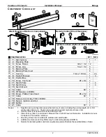
If 110V power is not available to the coach, the Mirage awning
can still be safely retracted using the manual override. The
bypass may be accessed from inside the case on the motor
housing or from the top of the case above the motor housing.
To use the inside bottom access:
The awning must be open a
minimum of 8” to afford access to the override.
To use the top bypass access
: Remove the screw and well nut
that is used to secure the end cap.
1. Chuck the 7mm hex key into a 3/8” battery powered drill.
2. Insert the hex key into the manual override on the awning.
For the top access, it will be necessary to locate the hex by
feel; it is not visible with the key inserted in the hole.
3. Operate the drill in the forward (clockwise) direction to close
the awning. Reverse the drill to open the awning.
NOTE: When using the bottom override, the awning
can only be closed within 6-8”. It will be
necessary to use the top access to close the
awning completely.
4. When done, return the screw and well nut to the top of the case if removed.
A
DJUSTING THE
P
ITCH
CAUTION
D
URING INSTALLATION OR WHEN THE PITCH OF THE AWNING IS ADJUSTED
,
IT IS IMPORTANT THAT THE LEAD RAIL
IS PARALLEL TO THE AWNING HOUSING
.
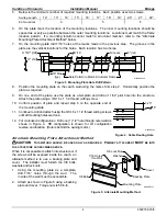
1. Extend the awning fully.
2. On one end, loosen the 6mm hex screw located on the spring
arm knuckle.
3. S
LIGHTLY
loosen the 3/4” nut on the side of the knuckle.
4. Turn the 3/4” adjustment nut located on the bottom of the knuckle.
C
LOCKWISE
raises the pitch,
COUNTERCLOCKWISE
lowers the pitch.
NOTE: When raising the pitch, it is helpful to have a
second person lift up on the lead rail.
5. Repeat steps 2 through 4 for the other end. Note the caution
information above.
6. When the pitch adjustments are completed, tighten the 6mm
screw and the 3/4” nut on the side of the knuckle.
When the pitch is adjusted, it is necessary to adjust the angle of
the lead rail for the awning to close correctly.
7. S
LIGHTLY
loosen the 3/4” nut on the side of each arm knuckle
on the lead rail.
8. Turn
the
INSIDE
6mm hex screws of each knuckle to increase
or decrease the angle of the lead rail. The face of the lead rail
should be parallel with the coach wall.
9. When the lead rail adjustments are completed, tighten the 3/4” nut on the side of the knuckles.
Wall
Bottom View
MIRAGE028
Wall
Top View
7mm Hex
Manual Override
Remove Screw
and Rubber Well Nut
to Access Manual
Overide (7mm Hex)
Figure 13. Manual Override Access.
Coach Wall
3/4” Adjustment Nut
6mm Hex Screw
MIRAGE024
3/4” Nut
On Side of Knuckle
3/4” Nut
6mm Hex Screw
Lead Rail (ref)
Figure 14. Pitch Adjustment.


