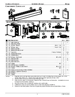
background image

Carefree of Colorado  

Installation Manual 

Mirage 

 4 

052979-003r5 

5. 

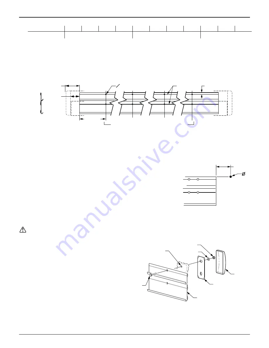
Below is the minimum number of required mounting locations.  Each position uses two screws. 

Awning Length 

12' 13' 14' 15' 16' 17' 18' 19' 20' 21' 22' 

# of Locations 

4 5 


6. 

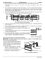
On the plate mark the location of the mounting locations.  The inner mounting locations should be 
spaced as evenly as possible between the outer mounting locations.  Locations must match the frame 
location pattern.  If a mounting location cannot match a structural member, refer to the "Alternate 
Mounting Plate Attachment Method" below. 

7. 

On the mounting plate drill 7/16” holes at the marks made in the previous step.  The grooves in the 
plate are the vertical locations for the holes.  Each location has two holes. 

Grooves 

.5" (ref) 

MIRAGE004b 

O 7/16” 

3" (ref) 

4 1/2" (ref) 

18” Max 

(typ) 

Hole Pattern to Match Structural Frame 


Figure 3.  Mounting Plate Hole Drill Pattern. 

8. 

Position the mounting plate on the coach wall using the marks from step 2.  Horizontally position the 
plate as required. 

9. 

On one end of the plate, use the plate as a template and drill an 11/32” pilot hole into the structure.  
Attach the plate using a 3/8-16 x 1 1/2 thread cutting screw. 

10.  Confirm position of plate and repeat step 6 on the opposite end of 

the mounting plate. 

11.  Continue to drill and attach using the 3/8-16 x 1 1/2 thread cutting screws 

until all mounting holes are done. 

12. 

For motorized configurations.

  Drill one (1) 1/2” hole through outer wall as 

shown in Figure 4.  RH configuration is shown, for LH configuration 
reverse end location.  (Hole is behind the awning motor.) 


Alternate Mounting Plate Attachment Method 

CAUTION  

T

HIS METHOD SHOULD BE USED ONLY AS REQUIRED

.


P

RIMARY ATTACHMENT 

MUST

 BE INTO 

THE STRUCTURE AS DESCRIBED ABOVE

.


When it is not possible to attach into structure or if 
the screws will be exposed inside the coach, an 
alternate method is to use a backing plate and 
cover.  The installer must furnish the 3/8 bolts, 
washers and lock nuts. 

1.  Using the mounting plate as a template, 

drill 7/16” holes through the wall.  The 
inside of the wall must be accessible. 

2.  Attach as shown in Figure 5 using a backing 

plate and cover.  Torque nuts to 50 in-lb. 


3.25"

.5"

MIRAGE005


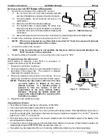
Figure 4.  Cable Routing Hole. 

Mounting Plate

3/8 Bolt

Cover

Backing Plate

Washer

3/8 Lock Nut

7/16 Holes

thru Wall

MIRAGE014


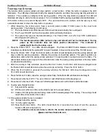
Figure 5.  Alternate Mounting Method. 

Содержание MIRAGE

Страница 1: ...Plate Attachment Method 4 Mounting the Awning Unit 5 Securing the Awning 5 Electrical Installation 6 Important Notices 6 Switch Installation 6 Control Box Installation 7 Installing the RF Remote Receiver 8 Programming the Receiver 8 Operational Notes 8 Ignition Lockout Sensor Installation Optional 9 Wiring Diagram Direct Response System 10 Testing the System 11 Standard System Adjustments 12 Manua...

Страница 2: ...translation of this document in whole or part is strictly prohibited without prior written approval from Carefree of Colorado SAFETY INFORMATION WARNING A WARNING INDICATES A POTENTIALLY HAZARDOUS SITUATION THAT IF NOT AVOIDED COULD RESULT IN DEATH OR SERIOUS INJURY AND OR MAJOR PROPERTY DAMAGE CAUTION A CAUTION INDICATES A POTENTIALLY HAZARDOUS SITUATION THAT MAY CAUSE MINOR TO MODERATE PERSONAL ...

Страница 3: ...the Direct Response system Two configurations of the Mirage awning are available a RH passenger side and a LH driver s side The motor is located to the front of the awning reducing wiring to keep the awning controls to the front of the vehicle In the Wiring Diagram the RH configuration is shown detail A shows the alterations for the LH configuration Mirage Patio Awning Specifications The following...

Страница 4: ... 133mm 1 2 3 8 Owner s Manual 1 3 9 Control Box 1 10 Screw Pan Head 8 x 3 4 4 11 Switch Plate 1 4 12 Switch Assy 1 4 13 Switch Mount 1 14 Cable 60 1 15 RF Receiver 433MHz 1 16 Screw Phillips Truss Head 6 x 1 2 2 17 Cable 60 1 18 Remote Control Key FOB 433MHz 1 5 19 Sensor Ignition Lock Out 1 20 Splitter 1 21 Cable 60 2 Notes 1 Specific awning configuration is specified at time of order including t...

Страница 5: ...zed fuse circuit breaker Each patio awning draws a maximum of 3 amps MOUNTING PLATE LAYOUT AND INSTALLATION 1 Determine the location of the awning Mounting area must be plumb and clear of obstacles The mounting plate is 9 shorter than the awning w standard end caps 6 shorter than the back plate Reference Figure 1 The awning is factory set with minimum pitch Mounting height above a door opening or ...

Страница 6: ...an 11 32 pilot hole into the structure Attach the plate using a 3 8 16 x 1 1 2 thread cutting screw 10 Confirm position of plate and repeat step 6 on the opposite end of the mounting plate 11 Continue to drill and attach using the 3 8 16 x 1 1 2 thread cutting screws until all mounting holes are done 12 For motorized configurations Drill one 1 1 2 hole through outer wall as shown in Figure 4 RH co...

Страница 7: ...5 16 1 4 x 1 1 2 Lag Screw 3 plcs MIRAGE010 Figure 7 Securing the Awning 1 Adjust the awning horizontally as required 2 Open the awning approximately 3 feet to access the back panel of the awning case 3 Drill three 3 3 16 holes through the case mounting plate and into wall do not go through interior surfaces of wall in the approximate areas shown above 4 Ream out the holes in the case only to 5 16...

Страница 8: ...installed An RF remote control is provided with the Direct Response system An optional ignition lockout is available The switches use a 5VDC signal to operate the control box eliminating the need for a junction box for the control panel Components are connected using terminated cables Terminated cable is 4 wire RJ11 terminated phone cord straight no twist This does not include 110VAC power connect...

Страница 9: ...sized fuse circuit breaker Each patio awning draws a maximum of 3 amps Connect wires to the control box as shown in the wiring diagram 4 Splice the awning motor wires to a 3 conductor 14AWG NM wire w ground Refer to note 1 on the wiring diagram on page 9 5 Route the cable wire from the motor to the control box and attach the wires to the terminals as shown NOTE For RH motor configurations RED WIRE...

Страница 10: ...ode when the red light comes on 3 Press and release the stop button on the remote The red light will go out after the receiver learns the remote signal NOTE Pressing the stop button will cause the blue up arrow button to default as the close retract function If a function button is pressed to train the receiver it will be programmed as the close retract button Example Pressing the bottom button wi...

Страница 11: ...wning Applications 4 1 Disconnect the remote receiver cable from the EYE port in the control box Do not disconnect the cable from the receiver box 4 2 Connect the supplied 6 cable to EYE port in the control box 4 3 Attach the splitter to the other end of the cable 4 4 Plug the cable from the remote receiver into the splitter 4 5 Attach the Lock Out Sensor to the end of the 60 cable Route the cable...

Страница 12: ...hes past the point of entry NOTES 4 Wires for the Ignition Lock Out Sensor are not pin specific 5 Splitter is used only when Optional Lock Out Sensor is installed Connect RF Receiver directly to EYE if Lock Out is not installed Detail A For LH Configuration Reverse Red Black Wires RED WHT BLK GRN grn wht blk RH Motor Wire Shown See Detail A for LH Motor For early units Label DSK was ACC Label EYE ...

Страница 13: ...he 110VAC power 3 Press the POWER ON Press the EXTEND button the LED should illuminate while the awning extends and stay on after the awning auto stops Observe the awning it should fully extend The system performs an auto tension action when the awning is fully extended The awning rolls in reverse to tension the fabric The auto tension feature works only with the extend function when the awning is...

Страница 14: ...S ADJUSTED IT IS IMPORTANT THAT THE LEAD RAIL IS PARALLEL TO THE AWNING HOUSING 1 Extend the awning fully 2 On one end loosen the 6mm hex screw located on the spring arm knuckle 3 SLIGHTLY loosen the 3 4 nut on the side of the knuckle 4 Turn the 3 4 adjustment nut located on the bottom of the knuckle CLOCKWISE raises the pitch COUNTERCLOCKWISE lowers the pitch NOTE When raising the pitch it is hel...

Страница 15: ...NOTE During normal operation the awning will extend out then roll back slightly to tension the fabric 1 Extend the awning out completely 2 Confirm that the arms are fully extended The motor should stop and the fabric should be tight 3 If the motor continues to run the fabric will sag use a 4mm allen wrench to turn the OUT limit switch to DECREASE the motor run time 4 If the motor quits before the ...

Отзывы: