Carefree of Colorado
Installation Manual
Mirage
6
052979-003r5
E
LECTRICAL
I
NSTALLATION
WARNING
A
LWAYS DISCONNECT THE VEHICLE BATTERY AND ELECTRICAL SOURCES BEFORE
WORKING WITH ELECTRICAL WIRING AND COMPONENTS
.
These instructions are for the Direct Response Auto-Retract System. For alternate control systems, follow
the directions included with the electronics package.
I
MPORTANT
N
OTICES
:
Failure to follow the wiring instructions in this publication may void the motor warranty.
All wiring must conform to NEC (National Electrical Code) and local codes.
D
O NOT
wire two or more motors to one switch—No parallel wiring.
The SO cable from the 110VAC awning motor can only pass directly through a wall, it can not be
laid up in the wall and must be connected to NM wire or individual wires in conduit no more than
6 inches past the point of entry.
The installer must provide enclosed junction boxes for all 110VAC wire splices. Boxes are
required in conformance with prevailing construction codes. Installers are required to furnish
the flush mounted, UL approved electrical duplex boxes where required.
The
Direct Response
electronic system is a premier auto-retract system that detects motion from adverse
wind conditions and retracts the awning. Sensitivity is set by the user.
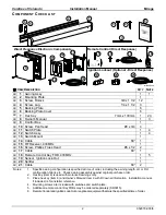
System includes: Control box, Master control panel (w/ pushbutton awning control and windspeed
sensitivity setting), motion sensor (factory installed).
An RF remote control is provided with the
Direct Response
system.
An optional ignition lockout is available.
The switches use a 5VDC signal to operate the control box; eliminating
the need for a junction box for the control panel.
Components are connected using terminated cables. Terminated cable
is 4-wire RJ11 terminated phone cord (straight, no twist). This does not
include 110VAC power connections.
NOTE: Cable lengths of the furnished cables are listed in the chart with the
system wiring diagram. If a connection requires a length greater
than the supplied cable, the installer must provide a terminated
jumper cable from the box location to the cable end. Terminated
cables are 4-wire RJ11 terminated phone cord (straight, no twist).
S
WITCH
I
NSTALLATION
1. At the switch location, cut a 4” x 3 3/4” rectangular
hole. The mounting box is able to clamp to
thicknesses from 1/4” to 1”.
2. Insert the mounting box and tighten the latch tab
screws. The tabs will automatically rotate to clamp
on the back side of the mounting surface. Do not
over tighten the clamp screws.
3. Mount the Patio and Wind Speed Switches in the
mounting box.
4. Mount the faceplate onto the switches. It may be
necessary to slightly loosen the switches to align the
faceplate and switches.
5. Connect the switch cable to the patio switch and
route to the location of the control box.
Black
Red
Green
Black
Yellow
Red
Green
Yellow
Cables are 4-wire RJ11
terminated phone cord
(straight, no twist).
RTA031
MIRAGE022a
4”
3 3/4”
Face Plate
Wind Speed
Switch
Patio
Switch
Mounting Box
Switch Cable to
Control Box
Latch Tab
Figure 8. Switch Installation.


