


Version 17.02.2020
HW: 32
CI-VL2-UCON8-AO
P
a
g
e
12
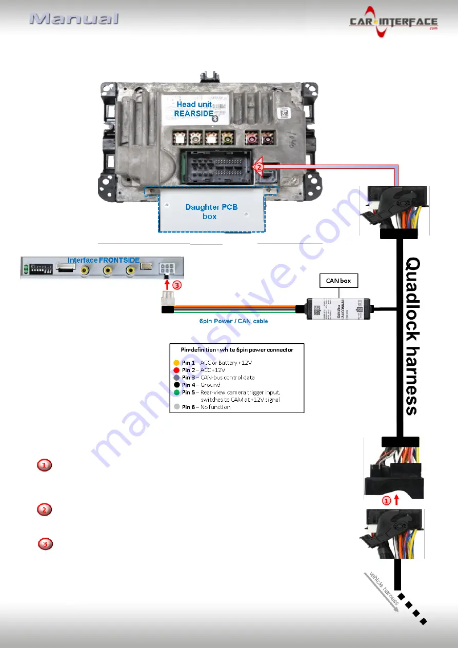
2.4.
Connections to the head-unit - Quadlock
Remove the female Quadlock connector of the vehicle harness from the rear of
the head unit and connect it to the male Quadlock connector of the Quadlock
harness.
Connect the opposite female Quadlock connector of the Quadlock harness to
the male Quadlock connector of the head-unit.
Connect the femal 6pin connector of the Power /CAN cable
to the 6pin connector of the video interface.


