Chapter 5
5-7
T-5-6
5.3.2 Adjustment at Time of Parts Replacement
5.3.2.1 Adjusting Position of Tray A, B
0021-1705
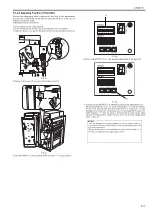
Execute this adjustment to keep the tray parallel when replacing tray A or
tray B.
Adjusting method is as follows:
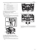
1) While keeping the tray horizontal, put the tray into the rails (left and right).
Be sure to have same distance at distance A (length from the tip [3] of the
rail to the tray shaft [4]) between the front side [1] and the rear side [2] of
the tray when installing the tray.
F-5-24
5.3.2.2 Right Angle Adjustment of Alignment Plate
0021-1706
Execute this adjustment when replacing the alignment motor in the interme-
diate process tray assembly or EEPROM on the finisher controller PCB.
Adjusting method is as follows:
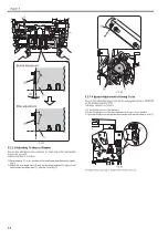
1) After installing the intermediate process tray assembly, loosen the 2
screws [2] on the alignment plate [1] in the intermediate process tray as-
sembly.
F-5-25
2) Secure the 2 paper edge stoppers [1] with the 2 screws [2].
F-5-26
3) After setting A4 paper [1] in the arrow direction of the intermediate tray
assembly, make adjustment so that there is no gap between the paper edge
[1] and the alignment plate [2], and then secure the alignment plate with
the screw [3].
Code
Number
Sensor Name
1
Buffer path 1 sensor PCB (UN13)
2
Buffer path 2 sensor PCB (UN14)
3
Lower path sensor PCB (UN24)
4
Side registration sensor PCB (UN12)
5
Punch waste full level sensor PCB (UN21)
6 to 8
Tray A paper surface sensor (UN16)
9, A, b
Tray B paper surface sensor (UN18)
[3]
[4]
[A]
[1]
[2]
[1]
[2]
[2]
[2]
[1]
Содержание Saddle Finisher-AF2
Страница 1: ...SERVICE MANUAL Saddle Finisher AF2 MARCH 6 2009...
Страница 2: ......
Страница 6: ......
Страница 12: ...Contents...
Страница 13: ...Chapter 1 Specifications...
Страница 14: ......
Страница 16: ......
Страница 22: ......
Страница 23: ...Chapter 2 Installation...
Страница 24: ......
Страница 26: ......
Страница 55: ...Chapter 3 Functions...
Страница 56: ......
Страница 58: ......
Страница 104: ...Chapter 3 3 46...
Страница 105: ...Chapter 4 Parts Replacement Procedure...
Страница 106: ......
Страница 110: ......
Страница 157: ...Chapter 4 4 47 F 4 213 3 2 1...
Страница 158: ......
Страница 159: ...Chapter 5 Maintenance...
Страница 160: ......
Страница 209: ...Chapter 5 5 47 F 5 221 SW382 SW381 SW383 ENTER SW384 SW385 DSP381 1...
Страница 217: ...Chapter 5 5 55 3 Door switch tool Front door switch ON tool number FY9 8006 No Name Description Composition Remarks...
Страница 218: ......
Страница 219: ...Appendix...
Страница 220: ......
Страница 221: ...General Timing Chart General Circuit Diagram Finisher Sorter DeliveryTray Saddle Finisher AF2...
Страница 222: ......
Страница 224: ......
Страница 225: ...Contents 1 General Circuit Diagram 1 Signal Names 1 General Circuit Diagram 9...
Страница 226: ......
Страница 243: ......
Страница 244: ......


