background image

Chapter 3

3-33

F-3-41

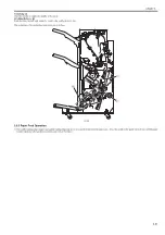
Roller guide clearance control

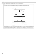
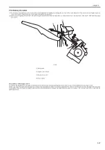
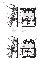
In case of thin paper (under 62 g/m2) if the clearance between the roller guide and the saddle process tray is too loose, the paper stack gets loose and the alignment

operation does not function properly. Thus, in case of thin paper mode, the machine makes the clearance [A] between the roller guide and the saddle process tray

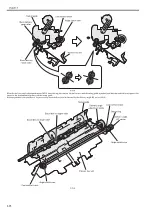
tighter compared with the modes other than thin paper. Also, the machine makes the clearance [A] larger when several sheets of paper are transferred to the saddle

process tray. The machine enlarges the clearance [A] by the specified degree per 5 sheets of paper.

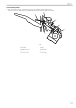
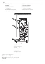
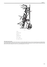
[1] Paper

[2] Saddle inlet roller

[3] Pull roller

[4] Alignment roller

[5] Process stopper

PS101: Saddle inlet roller

[1]

PS101

[2]

[3]

[4]

[5]

Содержание Saddle Finisher-AF2

Страница 1: ...SERVICE MANUAL Saddle Finisher AF2 MARCH 6 2009...

Страница 2: ......

Страница 3: ...need arises In the event of major changes in the contents of this manual over a long or short period Canon will issue a new edition of this manual The following paragraph does not apply to any countri...

Страница 4: ...uiring care to avoid combustion fire Indicates an item prohibiting disassembly to avoid electric shocks or problems Indicates an item requiring disconnection of the power plug from the electric outlet...

Страница 5: ...ed to indicate Low The voltage value how ever differs from circuit to circuit In addition the asterisk as in DRMD indicates that the DRMD signal goes on when 0 In practically all cases the internal me...

Страница 6: ......

Страница 7: ...with the the Professional Puncher Integration Unit 2 11 2 3 7 Connecting with the Paper Folding Unit 2 13 2 3 8 Connecting with the High Capacity Stacker 2 16 2 3 9 Connecting with the Perfect Binder...

Страница 8: ...2 4 2 1 Rear Cover 4 2 4 2 1 1 Removing the Rear Cover 4 2 4 2 2 Rear Upper Cover 4 3 4 2 2 1 Removing the Rear Upper Cover Right 4 3 4 2 2 2 Preparation for Removing the Rear Upper Cover Left 4 3 4...

Страница 9: ...gnment Motor 4 17 4 3 9 2 Removing the Saddle Alignment Motor 4 17 4 3 10 Tray Shift Motor 4 17 4 3 10 1 Removing the Tray A B Shift Motor 4 17 4 3 11 Shift Motor 4 18 4 3 11 1 Preparation for Removin...

Страница 10: ...41 4 5 1 1 Preparation for Removing Feed Motor Driver PCB 4 41 4 5 1 2 Remove the Feed Motor Driver PCB 4 41 4 5 2 Finisher Controller PCB 4 41 4 5 2 1 Finisher Controller PCB 4 41 4 5 3 Static Charg...

Страница 11: ...14 Adjusting Position of Saddle Lead Edge Stopper 5 23 5 3 2 15 Adjusting Position for Saddle Alignment Width 5 24 5 3 2 16 Adjustment After Replacing EEPROM IC107 on Finisher Controller PCB 5 26 5 3...

Страница 12: ...Contents...

Страница 13: ...Chapter 1 Specifications...

Страница 14: ......

Страница 15: ...Contents Contents 1 1 Product Specifications 1 1 1 1 1 Specifications finisher 1 1 1 1 2 Specifications saddle stitcher 1 2 1 2 Names of Parts 1 4 1 2 1 External View 1 4 1 2 2 Cross Section 1 5...

Страница 16: ......

Страница 17: ...A4 A4R A3 B4 B5 11 x 17 LGL LTR LTRR EXEC 1 000 sheets 100 sets or 147 mm in height Tray B A4 A4R B5 LTR LTRR EXEC 2 000 sheets 100 sets or 285 mm in height A3 B4 11 x 17 LGL 1 000 sheets 100 sets or...

Страница 18: ...ize 182 mm x 182 mm to 330 2 mm x 487 7 mm Weight 52 to 300 g m2 Type Thin Plain Heavy Recycled Coulor Pre punched Bond Paper Labels Transparency Tab Paper Coated Texture Paper Vellum 1 Point Stapling...

Страница 19: ...mode cannot be used with B5R 13 x 19 330 2 x 482 6 mm 12 x 18 304 8 x 457 2 mm or 12 5 8 x 17 3 4 320 x 450 mm Z fold mode When the optional Paper Folding Unit F1 is attached Tray A 20 sheets Tray B...

Страница 20: ...4 1 2 Names of Parts 1 2 1 External View 0020 3985 F 1 1 1 Tray B 5 Saddle delivery belt 2 Tray A 6 Upper cover 3 Top delivery outlet 7 Inlet transport unit 4 Bottom delivery outlet 8 Front cover 1 2...

Страница 21: ...er 4 Paddle 14 Shift roller 1 24 Sheaf delivery roller 5 Tray B 15 Inlet delivery roller 25 Pre press roller 6 Process feed roller 16 Saddle inlet delivery roller 26 Press unit 7 Tray A 17 Stapler 27...

Страница 22: ......

Страница 23: ...Chapter 2 Installation...

Страница 24: ......

Страница 25: ...5 Connecting with the Multi Drawer Document Insertion Unit 2 9 2 3 6 Connecting with the the Professional Puncher Integration Unit 2 11 2 3 7 Connecting with the Paper Folding Unit 2 13 2 3 8 Connect...

Страница 26: ......

Страница 27: ...1 In the case of unpacking in the room the following space is needed to unpack F 2 1 2 The following space is needed in the case of using slope board 1 Palette 2 Slope 3 Equipment F 2 2 CAUTION This...

Страница 28: ...Wire saddle 1pc 9 2 Screw RS tightening M4X10 10pc 10 3 Guide map label 1pc 11 4 Guide map label 1pc 12 Staple label 1pc 13 4 LED lamp label Products for South Korea and Taiwan 1pc 14 4 Saddle return...

Страница 29: ...bottom and slow ly bring the equipment down F 2 5 5 Lift the other side as well to remove the packing material 1 The plastic material 2 should be removed at the same time with Finisher AF1 only with S...

Страница 30: ...sher 0020 5493 1 Remove all the tapes affixed to the equipment 2 1 2 A B 1 1 2 2 CAUTION Proper order to turn ON the power when pickup delivery accessories are connected Be sure to follow the correct...

Страница 31: ...per cover 1 and remove the packing tapes 2 F 2 13 4 Close the upper cover 5 Pull out the saddle unit and remove the packing tapes 1 F 2 14 6 Put the saddle unit back 7 Remove the screw 2 on the latch...

Страница 32: ...d on the upstream equipment F 2 17 2 3 4 Connecting with the Host Machine 0020 6809 1 On the host machine s upper left side cover install the latch plate front 1 for rear 2 4 screws RS tightening M4X1...

Страница 33: ...e front 1 up fit the positioning pin 2 of the host machine into the positioning hole 3 of the finisher to connect the finisher with the host machine Front side F 2 20 Rear side F 2 21 4 Secure the lat...

Страница 34: ...screw 2 use the screw removed in step 7 Before Installing the Finisher F 2 23 7 Check the height between the finisher 1 and the host machine 2 F 2 24 8 Install the rear small cover 9 Install the shunt...

Страница 35: ...3 F 2 27 3 Fit the positioning pin 1 2 screws RS tightening M4X10 2 F 2 28 4 While lifting latch mount front 1 fit the Multi Insertion Unit side s po sitioning pin 2 into the positioning board s hole...

Страница 36: ...he finisher 7 Move the latch mount rear 1 in the direction of the arrow and insert it to the pin to fix it 1 screw 2 use the screw removed in step 7 Before Installing the Finisher F 2 32 8 Check the h...

Страница 37: ...3 F 2 35 2 Install positioning screw 1 2 screws RS tightening M4X10 2 F 2 36 3 While lifting latch mount front 1 fit the Integration Unit side s posi tioning pin 2 into positioning board s hole 3 of t...

Страница 38: ...alling the Finisher F 2 39 5 Close the front cover of the finisher 6 Move the latch mount rear 1 in the direction of the arrow and insert it to the pin to fix it 1 screw 2 use the screw removed in ste...

Страница 39: ...tightening M4X10 3 F 2 43 2 Fit the positioning pin 1 2 screws RS tightening M4X10 2 F 2 44 3 Remove the rear cover 1 8 screws 2 CAUTION Height difference should be within 2mm Execute Height Adjustme...

Страница 40: ...board s hole 3 of the Finisher to connect the Finisher with the Paper Folding Unit Front side F 2 46 Rear side F 2 47 5 Secure the latch plate front 1 1 screw 2 use the screw removed in step 5 Before...

Страница 41: ...le 1 2 Reuse band 2 2 spots Edge Saddle 3 F 2 50 9 Insert the connector 1 to the finisher controller PCB and fix the cable 2 3 wire saddles 3 F 2 51 10 Check the height between the finisher 1 and the...

Страница 42: ...ng M4X10 3 F 2 55 3 Fit the positioning pin 1 2 screws RS tightening M4X10 2 F 2 56 4 While lifting the latch plate front 1 up fit the High Capacity Stacker s positioning pin 2 into positioning board...

Страница 43: ...the screw removed in step 5 Before Installing the Finisher F 2 59 6 Close the front cover of the finisher 7 Move the latch mount rear 1 in the direction of the arrow and insert it to the pin to fix i...

Страница 44: ...252 1 On the Perfect Binder s upper left side install the latch plate front 1 for rear 2 4 screws RS tightening M4X10 3 CAUTION Height difference should be within 2mm Execute Height Adjustment if the...

Страница 45: ...up fit the Perfect Binder s position ing pin 2 of the host machine into the positioning hole 3 of the finisher to connect the finisher with the Perfect Binder Front side F 2 65 Rear side F 2 66 4 Secu...

Страница 46: ...7 Before Installing the Finisher F 2 68 7 Check the height between the finisher 1 and the Perfect Binder 2 F 2 69 8 Install the rear small cover 9 Remove the rear cover 1 of the Perfect Binder 5 scre...

Страница 47: ...1 2 screws RS tightening M4X10 2 F 2 73 3 While lifting latch mount front 1 fit the Document Insertion Unit side s positioning pin 2 into the positioning board s hole of the Finisher 3 to connect the...

Страница 48: ...ing the Finisher F 2 76 5 Close the front cover of the finisher 6 Move the latch mount rear 1 in the direction of the arrow and insert it to the pin to fix it 1 screw 2 use the screw removed in step 7...

Страница 49: ...Connect the terminal connector 2 and the ARCNET cable 3 to the co axial connector 1 and turn their knobs in the direction of the arrows as shown in the figure to secure CAUTION Height difference shoul...

Страница 50: ...on the rear cover of the finisher F 2 84 6 Bundle the ARCNET cable 1 with the wire saddle 2 If connected to Host Machine F 2 85 If connected to Multi Drawer Document Insertion Unit F 2 86 If connected...

Страница 51: ...F 2 91 7 Connect the power cable 1 to the finisher 1 2 1 2 1 2 CAUTION Note for Europe Asia Oceania Regions Use the correct power cord to mach the location area of installation Make sure not to leave...

Страница 52: ...height of the finisher and the host machine The height differ ence between the right top 1 of the finisher and the left top 2 of the host machine should be within 2mm F 2 93 3 If the difference excee...

Страница 53: ...e height rotate in the direction of A To lower the height rotate in the direction of B Height increment per rotation approx 1 75mm F 2 100 9 Tighten the fixing nut 1 in the direction of B F 2 101 10 A...

Страница 54: ...e unit 1 F 2 106 6 Affix the Saddle return attention label 1 F 2 107 7 Put the saddle unit back 8 Close the front cover of the finisher 2 6 Relocationg the Machine 2 6 1 A note on moving the machine 0...

Страница 55: ...Chapter 3 Functions...

Страница 56: ......

Страница 57: ...Correction Operation Shift Operation 3 10 3 4 5 Buffer Operation 3 13 3 4 6 Switching Over the Paper Path 3 15 3 4 7 Interval Speed Control 3 16 3 5 Intermediate Process Tray Assembly 3 18 3 5 1 Overv...

Страница 58: ......

Страница 59: ...ck and saddle stitcher block The electrical control block consists of 2 entities finisher controller PCB and saddle stitcher controller PCB Note F 3 2 The descriptions on the saddle stitcher block app...

Страница 60: ...and indicates the states of sensors and switches to the host machine F 3 4 The machine uses the following major ICs possessing specific functions IC Description CPU Controls the communications with t...

Страница 61: ...l 9 Auxiliary tray solenoid drive signal 4 Tray A paper detection signal 10 Tray B lift motor drive signal 5 Tray A paper surface detection light emitting signal 11 Tray B lift motor rotation detectio...

Страница 62: ...liary tray is moved by operating the solenoid SL9 according to the instructions from the finisher controller PCB F 3 7 1 Tray A lift motor drive signal 3 Tray B lift motor drive signal 2 Tray A lift m...

Страница 63: ...the tray to keep the top of the stack at a specific level When the tray becomes full of paper i e light blocked not reaching any of the 3 photosensors the finisher controller PCB switches over to a di...

Страница 64: ...very motor drive signal 10 Shift transport motor drive signal 4 Upper path switch solenoid drive signal 11 Horizontal registration detection unit shift motor drive signal 5 Buffer motor drive signal 1...

Страница 65: ...2 Lower path sensor signal 6 Shift unit trailing edge sensor detection signal 3 Upper delivery sensor signal 7 Inlet sensor signal 4 Buffer path 2 sensor signal PS3 Inlet sensor UN13 Buffer path 1 se...

Страница 66: ...heet stationary inside the transport block thereafter joins it with the subsequent sheet for forward movement 5 Movement Switch Over 5 Moves the paper to the stacking block or the saddle stitcher bloc...

Страница 67: ...sition during which UN12 detects the edge of paper to be moved The finisher controller PCB uses the results of the detection to compute the horizontal registration value F 3 13 1 Shift roller unit 4 S...

Страница 68: ...in to rotate 3 The finisher controller board computes the side registration correction value from the side registration detection results Then once the trailing edge of the paper clears the inlet feed...

Страница 69: ...ide registration shift Ref This causes the stacking position for each sheaf to change when the paper is output to the delivery tray 1 Shift roller unit 2 Side registration detection unit 3 Paper 1 Cor...

Страница 70: ...Chapter 3 3 12 F 3 17 At this time the degree of shift is decided after taking the side registration correction value into account 1 1 2 2...

Страница 71: ...bsequent sheet of paper using the buffer motor M4 and the buffer path switching solenoid SL1 with the help of the buffer path 1 sensor PCB and the buffer path 2 sensor PCB UN13 UN14 F 3 18 M4 Buffer m...

Страница 72: ...Chapter 3 3 14 The buffer operation takes place as follows when 3 sheets of paper are moved F 3 19 UN14 UN13 1 UN14 UN13 1 UN14 UN13 1 2 UN14 UN13 1 2 UN14 UN13 2 1 UN14 UN13 2 1 3 UN14 UN13 2 1 3...

Страница 73: ...roller PCB turns off or on the2 flappers upper delivery flapper lower delivery flapper to switch over the destination of paper F 3 20 1 From the host machine 5 Lower delivery flapper 2 Paper 6 To tray...

Страница 74: ...nlet roller 3 1300mm s 700mm s upper delivery Delivery motor M5 After feeding 84 5mm after the trailing edge of the paper sets the upper delivery sensor PS5 ON 4 700mm s 300mm s upper delivery Deliver...

Страница 75: ...0mm UN14 UN24 PS6 PS5 PS3 To tray A To tray B To tray A To tray B To tray A To tray B To tray A To tray B 10 mm 5 6 Lower delivery 1 1000 mm s 2 1300 mm s 3 1500 mm s 4 450 mm s 3 1 1 2 2 From host ma...

Страница 76: ...ngle adjustment motor drive signal 12 Staple motor drive signal 5 Swing guide motor drive signal 13 Staple motor shift drive signal 6 Paddle rotation motor drive signal 14 Process tray shift motor sig...

Страница 77: ...the front and the rear of the tray in shift mode 3 Stapling Operation 3 Staples a stack of sheets at a specific point in staple mode 4 Delivery Operation 4 Discharges the sheets deposited in the inte...

Страница 78: ...hine to support the paper When the trailing edge of paper goes through the feed belt the trailing edge drop plate hits the trailing edge of the paper to drop the paper to the process tray Also when a...

Страница 79: ...of the paper on the operation tray F 3 29 4 When the trailing edge of the paper reaches the operation stopper the stack delivery roller 1 and the paddle 2 stop rotating and the swing guide 1 is lifte...

Страница 80: ...alignment plate to the front rear to align the paper This operation is executed every time the paper is fed to the operation tray F 3 31 1 Paper 4 Operation stopper 2 Stack delivery roller 5 Swing gui...

Страница 81: ...ction of the arrow causing its lead edge to move away from the stopper The tray auxiliary plate is pushed outside the machine before delivery occurs to hold the lead edge of paper This prevents misali...

Страница 82: ...ray B only Tray A executes the alignment operation inside the feed assembly F 3 32 1 Alignment plate 2 Paper stack 3 Swing guide Shift Function The machine s alignment mechanism operates either of its...

Страница 83: ...moves down the swing guide and performs stapling Note 1 At this time if the process stopper position is overlapping that staple position the process stopper is moved away F 3 33 1 Swing guide 4 Staple...

Страница 84: ...e waste staple case is detected by the sensor When the waste staple in the case reaches the specified amount after approx 5000 times the case moves down The flag on the case blocks the sensor due to t...

Страница 85: ...per eject action F 3 34 Stack delivery roller angle control To enhance the productivity the paper is delivered to the delivery tray without passing the process tray in case of lower delivery in non st...

Страница 86: ...s the position of the process tray lower delivery and is detected by the delivery angle HP sensor PS45 F 3 36 Stack delivery upper roller Stack delivery lower roller Swing guide Angle switch cam Proce...

Страница 87: ...otor drive signal 9 Saddle transport motor drive signal 10 Saddle paper butting plate signal 11 Saddle alignment motor drive signal 12 Saddle lead edge stopper motor drive signal 13 Saddle trailing ed...

Страница 88: ...cher motor M110 Saddle trailing edge holding motor M111 Saddle trailing edge moving motor M112 Saddle alignment roller motor M113 Saddle tapping motor M114 Saddle lead in roller disengage motor SL103...

Страница 89: ...saddle delivery tray The particulars of the individual operations are as follows F 3 39 3 6 3 Paper Feed Operation 0020 4852 1 The saddle leading edge stopper and saddle trailing edge stay move into...

Страница 90: ...he paper the saddle alignment roller rotates and drives the saddle pull roller disengage motor and the saddle align ment roller disengage solenoid so that the paper is transported by the pull roller a...

Страница 91: ...paper mode the machine makes the clearance A between the roller guide and the saddle process tray tighter compared with the modes other than thin paper Also the machine makes the clearance A larger wh...

Страница 92: ...e shutter shift mount at the first time it moves with the constant clearance A When it continues lifting it reaches the edge of the shutter shift mount and the clearance A is reduced as it moves In th...

Страница 93: ...lignment roller and lead in roller It then narrower the alignment guide in accordance with the paper size to align the paper stack Saddle process tray Roller guide Shutter shift mount Shutter shift mo...

Страница 94: ...paper is pushed to the leading edge stopper and then the knocking plate taps the trailing edge of paper F 3 45 1 Pull roller 5 Tapping plate 2 Alignment roller 6 Trailing edge stay 3 Alignment guide...

Страница 95: ...ation on the paper 3 6 5 Staple Operation 0020 4854 1 There is one sticker unit at the front and the rear of the machine respectively When the alignment operation is complete and the trailing edge ret...

Страница 96: ...livery Operations 0020 4855 1 The saddle roller guide 1 is lowered and then the leading edge gripper solenoid Sl105 comes ON and the paper 3 is gripped by the gripper 2 F 3 48 1 Stitcher unit 2 Paper...

Страница 97: ...n 5 are aligned F 3 49 3 After the paper folding roller begins to rotate in the direction of the arrow the paper guide plate moves in the direction of the arrow This starts the paper folding operation...

Страница 98: ...Chapter 3 3 40 F 3 50 4 The sheaf transport roller and pre press roller begin to rotate forwards transporting the sheaf to the press unit 1 Paper sheaf 2 Paper guide plate 3 Paper fold roller 3 1 2...

Страница 99: ...n the direction of the arrow At this time the press pressure roller within the press unit begins to rotate and applies pressure onto the sheaf This action makes sure that the sheaf is properly folded...

Страница 100: ...nit has moved in the direction of the arrow the pre press roller begins to rotate once more This action delivers the sheaf to the saddle delivery belt F 3 53 3 Pre press roller 1 Paper sheaf 3 Press u...

Страница 101: ...nlet sensor stationary PS3 The paper doesn t come out from Inlet Sensor PS3 within the specified time distance after Inlet Sensor PS3 detects the paper and do the feeding 1103 Shift Unit Trailing Edge...

Страница 102: ...n the specified time distance after Buffer Path 2 Sensor UN14 detects the paper and do the feeding 100E Lower Delivery Sensor Stationary PS6 The paper doesn t come out from Lower Delivery Sensor PS6 w...

Страница 103: ...ensor Delay PS105 The Saddle Vertical Path Sensor PS105 doesn t detect the paper within the specific time after Saddle Push on Plate movement starts 1046 Saddle Vertical Path Sensor Stationary PS105 T...

Страница 104: ...Chapter 3 3 46...

Страница 105: ...Chapter 4 Parts Replacement Procedure...

Страница 106: ......

Страница 107: ...Install the Stack Wall Lower 4 8 4 2 7 Saddle Inside Cover 4 9 4 2 7 1 Remove the Saddle Inside Cover Upper 4 9 4 2 7 2 Removing the Saddle Inside Cover Lower 4 9 4 2 8 Inside Cover Upper 4 9 4 2 8 1...

Страница 108: ...for Engaging Roller 4 24 4 4 1 2 Removing the Engaging Roller 4 25 4 4 2 Stack Delivery Roller 4 25 4 4 2 1 Preparation for Removing Stack Delivery Upper Roller 4 25 4 4 2 2 Removing Stack Delivery U...

Страница 109: ...he Stack Delivery Roller Upper Static Charge Eliminator 4 42 4 5 3 3 Preparation for Removing the Stack Delivery Roller Lower Static Charge Eliminator 4 42 4 5 3 4 Removing the Stack Delivery Roller L...

Страница 110: ......

Страница 111: ...he host machine F 4 2 3 Removing rear small cover 1 as the direction of the arrow 1 screw 2 2 hooks 3 F 4 3 4 Tilt the hinge 1 of the latch mount rear as the direction of the arrow 1 screw 2 CAUTION I...

Страница 112: ...rew 2 from the latch mount front 1 F 4 5 7 While lifting the latch mount front 1 disconnect the finisher from the host machine F 4 6 4 2 External Covers 4 2 1 Rear Cover 4 2 1 1 Removing the Rear Cove...

Страница 113: ...ft 1 4 screws 2 F 4 9 4 2 3 Upper Cover Unit 4 2 3 1 Preparation for Removing Upper Cover Unit 0020 7825 1 Remove the rear upper cover right page 4 3 Reference Removing the Rear Upper Cover Right 2 Re...

Страница 114: ...2 4 Delivery Tray 4 2 4 1 Preparation for Removing the Tray A B Unit 0020 7827 1 Remove the rear upper cover right page 4 3 Reference Removing the Rear Upper Cover Right 2 Remove the rear upper cover...

Страница 115: ...2 F 4 17 3 Remove the reinforcement plate 1 on the rear side 4 screws 2 F 4 18 4 Remove the cable 1 2 screws 2 1 tooth washer 3 2 connectors 4 1 wire saddle 5 F 4 19 6 Remove the 2 screws 1 pull out...

Страница 116: ...Remove the Tray B Unit 1 Remove the stopper middle 1 1 screw 2 F 4 23 2 Remove the cable 1 1 screw 2 1 tooth washer 3 1 connector 4 F 4 24 3 Remove the 2 screws 1 pull out the cable as the direction...

Страница 117: ...AUTION Do not hit the upper cover 1 during the tray removal 1 2 1 1 CAUTION When installing tray A B unit be sure that the cables don t entangle CAUTION Do not get the stack wall rail 1 scratch or hav...

Страница 118: ...2 6 Stack Wall Lower 4 2 6 1 Preparation for Removing the Stack Wall Lower 0020 8346 1 Remove the stack wall upper page 4 8 Reference Removing the Stack Wall Upper 4 2 6 2 Removing the Stack Wall Lowe...

Страница 119: ...he saddle inside cover upper 1 1 knob 2 2 screws 3 F 4 34 4 2 7 2 Removing the Saddle Inside Cover Lower 0020 8351 1 Open the front cover 2 Remove the saddle inside cover lower 1 1 knob 2 4 screws 3 F...

Страница 120: ...emoving Buffer Motor 0020 8849 Remove the rear upper cover right page 4 3 Reference Removing the Rear Upper Cover Right 2 Remove the rear upper cover left page 4 3 Reference Removing the Rear Upper Co...

Страница 121: ...t feed Motor 0020 8854 Remove the rear cover page 4 2 Reference Removing the Rear Cover 4 3 2 4 Removing the Inlet Feed Motor 0020 8855 1 Remove the cable 1 1 edge saddle 2 2 wire saddles 3 F 4 44 2 R...

Страница 122: ...e Unit 0020 8355 1 Remove the inside cover upper page 4 9 Reference Removing the Inside Cover Upper 2 Remove the insede cover lower page 4 10 Reference Removing the Inside Cover Lower 4 3 5 2 Removing...

Страница 123: ...ignment Motor 0020 8359 1 Remove the stack wall upper page 4 8 Reference Removing the Stack Wall Upper 2 Remove the stack wall lower page 4 8 Reference Removing the Stack Wall Lower 3 Remove the proce...

Страница 124: ...Remove the process tray plate unit 1 1 screw 2 Loosen 1 belt 3 6 screws 4 2 positioning plates 5 F 4 59 5 Remove the process tray alignment plate front 1 1 screw 2 1 claw 3 CAUTION Before performing s...

Страница 125: ...or 4 3 8 1 Preparation for Removing the Rear Alignment Motor 0020 8361 1 Remove the stack wall upper page 4 8 Reference Removing the Stack Wall Upper 2 Remove the stack wall lower page 4 8 Reference R...

Страница 126: ...Remove the process tray plate unit 1 1 screw 2 Loosen 1 belt 3 6 screws 4 2 positioning plates 5 F 4 67 5 Remove the process tray alignment plate rear 1 1 screw 2 1 claw 3 CAUTION Before performing s...

Страница 127: ...21 6250 1 Pull out the saddle unit service position page 4 32 Reference Pull Out the Saddle Unit Service Position 2 Remove the saddle inside cover lower page 4 10 Reference Remov ing the Inside Cover...

Страница 128: ...Reference Removing From the Host Machine 2 Remove the rear upper cover right page 4 3 Reference Removing the Rear Upper Cover Right 3 Remove the rear upper cover left page 4 3 Reference Removing the...

Страница 129: ...emove the latch mount support plate 1 2 screws 2 F 4 79 3 Remove the rear cover support plate 1 3 screws 2 F 4 80 4 Remove the feed stay right upper 4 screws 2 F 4 81 5 Remove 2 connectors 1 and 2 scr...

Страница 130: ...on of the arrow 2 screws 2 F 4 83 7 Remove the flexible cable 1 F 4 84 8 Remove the 5 connectors 1 F 4 85 9 Remove the cable guide 1 1 screw 2 F 4 86 10 Remove the horizontal registration shift unit 1...

Страница 131: ...89 3 Remove the belt 1 then remove the side registration shift motor 2 2 screws 3 F 4 90 4 3 11 5 Preparation for Removing Shift Motor 0020 8364 1 Separate this machine from the connecting device of t...

Страница 132: ...e 1 4 connectors 2 7 wire saddle 3 1 reuse band 4 F 4 92 2 Remove the positioning plate unit 1 2 screws 2 F 4 93 4 3 13 Belt Controller Unit 4 3 13 1 Preparation for Removing Belt Controller Unit 0020...

Страница 133: ...ocess upper guide unit 1 F 4 98 6 Move the belt variable lever 1 as the direction of the arrow F 4 99 7 Remove 2 roller guides 1 as the direction of the arrow release 2 belts 2 from belt variable leve...

Страница 134: ...ocument Feeding System 4 4 1 Engaging Roller 4 4 1 1 Preparation for Engaging Roller 0020 8573 1 Remove the saddle staple unit page 4 12 Reference Removing the Saddle Staple Unit 1 1 2 3 4 1 2 CAUTION...

Страница 135: ...ngaging roller front 1 to the front direction 1 screw 2 F 4 108 6 After removing the separation roller front from the engaging roller rear remove the engaging roller front as the procedure 4 4 2 Stack...

Страница 136: ...delivery roller 1 F 4 114 4 4 3 Process Tray Assembly 4 4 3 1 Preparation for Removing the Process Tray Assembly 0020 8581 1 Remove the stack wall upper page 4 8 Reference Removing the Stack Wall Upp...

Страница 137: ...om the host machine through the hole of the frame and remove the process tray assembly 1 4 A 2 3 1 3 3 2 2 After removing the process tray assembly put 4 places of the protrusion 1 in the frame on the...

Страница 138: ...ay Assembly 4 4 4 2 Removing the Process Tray Front 0020 8605 1 Move the process tray alignment plate front 1 a little as the direction of the arrow remove the screw 2 claw 3 and remove the process tr...

Страница 139: ...Lower 3 Remove the process tray assembly page 4 26 Reference Removing the Process Tray Assembly 4 4 5 2 Removing the Feed Belt 0020 8609 1 Remove the guide 1 1 screw 2 F 4 121 2 Loosen the screw 1 mo...

Страница 140: ...Upper 3 Remove the process tray assembly page 4 26 Reference Removing the Process Tray Assembly 4 Remove the rear cover page 4 2 Reference Removing the Rear Cover 5 Remove the inner cover upper page...

Страница 141: ...lease the delivery roller shaft 1 1 and remove the belt roller 2 F 4 131 How to remove the rear belt roller 6 Remove the E ring 1 F 4 132 7 Shift the gear 1 and remove the parallel pin 2 Note Points t...

Страница 142: ...he position where the screw fits remove the 3 paddle units 2 3 screws 3 F 4 136 4 4 7 Paddle 4 4 7 1 Preparation for Removing Paddle 0020 8728 1 Remove the stack wall upper page 4 8 Reference Removing...

Страница 143: ...0 5 Remove the cable guide 1 from the saddle unit and pull out the saddle unit further 3 connectors 2 1 screw 3 F 4 141 4 4 8 2 Removing the Saddle Unit 0020 8735 1 While move the saddle unit to the h...

Страница 144: ...e Alignment Roller 0021 6254 1 Pull out the saddle unit service position page 4 32 Reference Pull Out the Saddle Unit Service Position 2 Remove the pressing unit page 4 36 Reference Removing the Press...

Страница 145: ...e the cable 1 from cable guide 2 12 connectors 3 F 4 150 5 Remove 2 connectors 1 wire saddle 2 in 3 places and edge saddle 3 on 3 places from the cable F 4 151 6 Remove the wire saddle 1 on 1 places f...

Страница 146: ...ew thrust plate adjust it to the position marked in step 2 and fix it 4 4 12 Pressing Unit 4 4 12 1 Preparation for Removing Pressing Unit 0020 8762 2 Pull out the saddle unit service position page 4...

Страница 147: ...pressing unit 1 F 4 164 4 4 13 Pressing Roller Unit 4 4 13 1 Preparation for Removing the Pressing Roller Unit 0020 8782 2 Pull out the saddle unit service position page 4 32 Reference Pull Out the Sa...

Страница 148: ...167 4 Remove the delivery guide lower 1 4 screws 2 F 4 168 5 Remove the belt support plate 1 1 screw 2 F 4 169 6 Remove the slide shaft lower 1 as the direction of the arrow 1 E ring 2 F 4 170 1 2 2...

Страница 149: ...ce position page 4 32 Reference Pull Out the Saddle Unit Service Position 2 Remove the saddle inside cover lower page 4 10 Reference Remov ing the Inside Cover Lower 3 Remove the pressing unit page 4...

Страница 150: ...ll bearing 3 and plate 4 F 4 179 7 Remove the unit fixing base rear 1 at the rear side of the saddle unit 2 screw 2 F 4 180 8 Remove the C ring 1 ball bearing 2 located in the rear side of the sad dle...

Страница 151: ...on for Removing Feed Motor Driver PCB 0021 4901 1 Remove the rear cover page 4 2 Reference Removing the Rear Cover 4 5 1 2 Remove the Feed Motor Driver PCB 0021 4902 1 Remove the feed motor driver PCB...

Страница 152: ...upper page 4 8 Reference Removing the Stack Wall Upper 2 Remove the stack wall lower page 4 8 Reference Removing the Stack Wall Lower 4 5 3 4 Removing the Stack Delivery Roller Lower Static Charge El...

Страница 153: ...f 2 saddle inlet roller static charge eliminators 1 F 4 197 4 5 3 8 Preparation for Removing the Feed Guide Lower Static Charge Eliminator 0020 8808 1 Remove the saddle staple unit page 4 12 Reference...

Страница 154: ...n Sensor Unit 0020 8946 1 Separate this machine from the connecting device of the host machine page 4 1 Reference Removing From the Host Machine 2 Remove the rear upper cover right page 4 3 Reference...

Страница 155: ...the 2 connectors 2 connected to the finisher controller 1 F 4 206 5 Remove the punch unit cable 1 1 edge saddle 2 1 cable guide 3 1 connector 4 CAUTION During the rear cover installation be sure that...

Страница 156: ...nce Removing the Rear Upper Cover Right 3 Remove the rear upper cover left page 4 3 Reference Removing the Rear Upper Cover Left 4 Remove the rear cover page 4 2 Reference Removing the Rear Cover 5 Re...

Страница 157: ...Chapter 4 4 47 F 4 213 3 2 1...

Страница 158: ......

Страница 159: ...Chapter 5 Maintenance...

Страница 160: ......

Страница 161: ...very 5 18 5 3 2 12 Adjusting Saddle Stitching Position 5 20 5 3 2 13 Adjusting Saddle Folding Position 5 22 5 3 2 14 Adjusting Position of Saddle Lead Edge Stopper 5 23 5 3 2 15 Adjusting Position for...

Страница 162: ...Contents 5 4 3 Solenoids Saddle Unit 5 53 5 4 4 PCBs Saddle Unit 5 54 5 5 Upgrading 5 54 5 5 1 Upgrading 5 54 5 6 Service Tools 5 54 5 6 1 Solvents and Oils 5 54...

Страница 163: ...aple cartridge replacement when prompted in host machine control panel 2 waste staple disposal when prompted in host machine control panel No Item Timing 1 staple cartridge replacement when prompted i...

Страница 164: ...in 2mm F 5 1 2 If the height difference is 2mm or more execute height adjustment 2 Height adjustment 1 Separate the finisher from the host machine 2 Remove the spanner 1 from the front cover 1 screw 2...

Страница 165: ...ove 11 Connect the finisher with the host machine again and check the height Install the covers and other parts removed in the previous steps if the height difference is within 2mm If not repeat the s...

Страница 166: ...ment mode If the adjustment value estimated value is within the range set the DIP switch back and complete the adjustment If the adjustment value estimated value is out of the range execute 2 Side reg...

Страница 167: ...ue again If the adjustment value indicated on the LED is within the range press ENTER button to complete the adjustment mode If the adjustment value indicated on the LED is out of the range execute ad...

Страница 168: ...shown in the figure 1 ON and then press ENTER SW385 button 2 to start adjustment for sensor light intensity F 5 22 6 Check that the LED 1 indicates with lighted 0 Press ENTER SW385 button 2 to complet...

Страница 169: ...process tray assembly or EEPROM on the finisher controller PCB Adjusting method is as follows 1 After installing the intermediate process tray assembly loosen the 2 screws 2 on the alignment plate 1 i...

Страница 170: ...king position 1 aligned and then secures the staple unit 2 with the 2 screws 3 F 5 28 5 3 2 4 Speed Adjustment of Swing Guide 0021 1709 Execute this adjustment when replacing the swing guide motor or...

Страница 171: ...cing the front alignment motor or the rear alignment motor or replacing EEPROM on the finisher controller PCB Adjusting method is as follows 1 Turn ON the power of the finisher 2 Turn ON the power swi...

Страница 172: ...pressing SW384 once the LED 3 indicates 1 and the front alignment plate 4 shifts to the rear by approx 0 2mm Adjustment range 10 to 10 shifting amount per unit 0 2mm F 5 39 9 Pressing push switch SW3...

Страница 173: ...f the feed belt F 5 45 7 Pressing switch SW383 1 or SW384 2 determines adjustment level By pressing SW383 once the LED 3 indicates 1 and the distance between the belt 4 and the sheet interval 5 is red...

Страница 174: ...ROM on the finisher controller PCB Adjusting method is as follows 1 Turn ON the power of the finisher 2 Turn ON the power switch of the host machine to be on standby 3 Open the front cover and put the...

Страница 175: ...is within the specified range 1 of 5 2mm using this result If the stapling position is out of the specification go through the procedure again from step 6 F 5 56 5 3 2 8 Adjusting Staple Position 1 st...

Страница 176: ...mines adjustment level By pressing SW383 once the LED 3 indicates 1 and the stapling position at the front shifts to the rear In the same way by pressing SW384 once the LED 3 indicates 1 and the stapl...

Страница 177: ...apling position 2 stapling positions or replacing EEPROM on the finisher controller PCB Adjusting method is as follows 1 Turn ON the power of the finisher 2 Turn ON the power switch of the host machin...

Страница 178: ...s shift to the lower side Adjustment range 20 to 20 shifting amount per unit 0 5mm F 5 71 8 Press switch SW385 1 to move the stapler to the 2 stapling position F 5 72 9 Place A4 paper 1 on the interme...

Страница 179: ...Set DIP SW382 1 on the switch PCB as shown in the figure below F 5 77 6 Pressing switch SW385 1 activates the LED 2 with 0 blinking The Adjustment is ready now F 5 78 7 Set 3 sheets of A3 size origin...

Страница 180: ...et and the 3rd sheet Pressing push switch SW383 2 reduces the displacement amount while pressing SW384 3 increases the displacement amount Correction amount is displayed on the LED 4 Adjustment range...

Страница 181: ...the start key on the control panel 9 Open the upper cover and measure displacement amount of the paper stack that is stopped at the buffer assembly displacement amount be tween the 1st sheet and the 2...

Страница 182: ...een the 1nd sheet and the 3rd sheet Pressing push switch SW383 2 reduces the displacement amount while pressing SW384 3 increases the displacement amount Correction amount is displayed on the LED 4 Ad...

Страница 183: ...g Note that if the push switch is pressed without the paper on the saddle unit the machine goes to the position adjustment mode mentioned in step 11 F 5 96 9 Take out the paper that you have set and m...

Страница 184: ...Specify the booklet with 2 sheets or more any on the control panel and make a copy 4 Spread the bound paper to measure the folding position 2 against the sta ple position 1 Adjustment is complete if...

Страница 185: ...emove the PCB cover 1 6 screws 2 F 5 106 3 Loosen the 2 fixing screws 1 of the lead edge stopper fixture by approx quarter turn F 5 107 4 Correct the position of the stopper fixture according to the d...

Страница 186: ...ion 3 Then press SW385 so that the adjustment is ready now F 5 111 6 Hold the lever 1 to pull out the saddle unit 2 and then open the saddle right guide 3 F 5 112 7 Set paper 2 on the saddle assembly...

Страница 187: ...Chapter 5 5 25 F 5 114 10 Press switch SW385 once to complete the adjustment mode SW382 SW381 SW383 ENTER SW384 SW385 DSP381 D D 3 4 2 1 A B...

Страница 188: ...g alignment plate position Right angle adjustment of alignment plate Adjusting staple position 1 stapling at the rear Adjusting staple position 1 stapling at the front Adjusting staple position 2 stap...

Страница 189: ...less of stacking method non staple stack staple stack Following describes the setup procedure of this mode 1 Turn ON the power of the finisher 2 Turn ON the power switch of the host machine to be on s...

Страница 190: ...n the intermediate process tray in the arrow direction and then measure displacement amount A between the paper edge stopper 2 and the assist stopper 3 If the measured value A or A is out of the speci...

Страница 191: ...from 1 to 2 so that the finisher is ready to work CAUTION If the reference value 3 measured in the previous step is A move the stopper 2 in the direction of the white arrow If the reference value 3 m...

Страница 192: ...cover 1 F 5 128 5 Set DIP SW382 1 on the switch PCB as shown in the figure below F 5 129 6 Press SW385 1 so that the height adjustment for staple inlet guide is ready now F 5 130 7 Pressing switch SW...

Страница 193: ...he switch cover 1 F 5 136 5 Set DIP SW382 1 on the switch PCB as shown in the figure below F 5 137 6 Press SW385 1 so that the height adjustment for the paddle is ready now F 5 138 7 Pressing switch S...

Страница 194: ...e on standby 3 Open the front cover and put the door switch tool into the door switch 1 F 5 143 4 Remove the screw 2 to remove the switch cover 1 F 5 144 5 Set DIP SW382 1 on the switch PCB as shown i...

Страница 195: ...t machine to be on standby 3 Open the front cover and put the door switch tool into the door switch 1 F 5 150 4 Remove the screw 2 to remove the switch cover 1 SW382 SW381 SW383 ENTER SW384 SW385 DSP3...

Страница 196: ...r as shown in the figure below or replacing EEP ROM IC107 on the finisher controller PCB F 5 156 Following describes the detailed adjustment method 1 Turn ON the power of the finisher 2 Turn ON the po...

Страница 197: ...s switch SW385 1 again to complete this adjustment F 5 162 5 3 2 24 Adjustment in the Case of Canceling Limit for Tray Stack 0021 1732 Execute this adjustment in the case of canceling the limit for tr...

Страница 198: ...itch SW385 1 so that this adjustment is ready now F 5 167 7 Pressing push switch SW384 1 once displays 1 on the LED 2 MEMO This adjustment is for the upper tray only Thus cancellation of the stacking...

Страница 199: ...screws 3 F 5 170 3 Remove the saddle inner cover lower 1 4 screws 2 1 knob 3 F 5 171 4 Turn ON the power of the finisher 5 Turn ON the power switch of the host machine to be on standby 6 Put the door...

Страница 200: ...e front 1 and the stapling position at the rear 2 In case of large displacement amount be sure to adjust tilt of the saddle staple unit by going through the following procedure F 5 180 15 Loosen the 2...

Страница 201: ...osition F 5 182 Adjusting method is as follows 1 Turn ON the power of the finisher 2 Turn ON the power switch of the host machine to be on standby 3 Open the front door and put the door switch tool in...

Страница 202: ...Press switch SW385 1 again to complete this adjustment F 5 189 9 Execute booklet print from the saddle and check that there is no displace ment in staple position 5 3 2 27 Adjusting Feeding Distance...

Страница 203: ...figure below F 5 193 6 Press switch SW385 1 so that this adjustment is ready now F 5 194 7 Pressing switch SW383 1 or SW384 2 determines adjustment level By pressing SW384 once the LED 3 indicates 1...

Страница 204: ...o remove the switch cover 1 F 5 198 5 Set DIP SW382 1 on the switch PCB as shown in the figure below F 5 199 6 Press switch SW385 1 so that this adjustment is ready now F 5 200 7 Press push switch SW3...

Страница 205: ...03 5 Set DIP SW382 1 on the switch PCB as shown in the figure below F 5 204 6 Press switch SW385 1 so that this adjustment is ready now F 5 205 7 Press push switch SW384 1 to execute setting F 5 206 S...

Страница 206: ...Chapter 5 5 44 F 5 207 In the case of upper curl F 5 208 8 Press switch SW385 1 again to complete this adjustment F 5 209 SW382 SW381 SW383 ENTER SW384 SW385 DSP381 1...

Страница 207: ...emove the screw 2 to remove the switch cover 1 F 5 211 5 Set DIP SW382 1 on the switch PCB as shown in the figure below F 5 212 6 Press switch SW385 1 so that this adjustment is ready now F 5 213 7 Pr...

Страница 208: ...0 Normal mode 1 Forcible 1 sheet through delivery mode all 2 Forcible stack delivery with buffer mode alignment is not performed 3 Forcible stack delivery without buffer mode alignment is performed on...

Страница 209: ...Chapter 5 5 47 F 5 221 SW382 SW381 SW383 ENTER SW384 SW385 DSP381 1...

Страница 210: ...Remove the screw 2 to remove the switch cover 1 F 5 223 5 Set DIP SW382 1 on the switch PCB as shown in the figure below F 5 224 6 Press switch SW385 1 so that this adjustment is ready now F 5 225 7...

Страница 211: ...7 3 Remove the spring 1 1pc each F 5 228 4 Loosen the screw 1 to adjust position of the stopper plate 3 by follow ing the scale of the engraved line 2 Engraved line A adjustment position at the time o...

Страница 212: ...05 Saddle lead edge stopper HP sensor To detect the saddle lead edge stopper HP WG8 5823 PS106 Saddle alignment plate HP sensor To detect the saddle alignment plate HP WG8 5823 PS107 Saddle roller gui...

Страница 213: ...feeder motor rotation WG8 5823 E5F1 PS115 Saddle press motor sensor To detect the saddle press motor rotation WG8 5823 PS116 Saddle press position sensor To detect the saddle press position WG8 5823 P...

Страница 214: ...or To move the saddle roller guide FK2 1731 M105 Saddle paper push on plate motor To drive the sallde paper push on plate FK2 7515 M106 Saddle folder feeder motor To drive the roller FK2 1734 E5F1 M10...

Страница 215: ...le tapping plate FK2 1731 E5FC M114 Saddle lead in roller disengage motor To disengage the saddle lead in roller FK2 1731 E5FB Notatio n Name Description Parts No SL103 Alignment roller disengage sole...

Страница 216: ...on Name Description Parts No Jam Error UN101 Saddle sticher controller PCB To control the saddle sticher unit UN125 Saddle sticher jam LED PCB To turn on the saddle sticher unit jam FG3 0535 No Name D...

Страница 217: ...Chapter 5 5 55 3 Door switch tool Front door switch ON tool number FY9 8006 No Name Description Composition Remarks...

Страница 218: ......

Страница 219: ...Appendix...

Страница 220: ......

Страница 221: ...General Timing Chart General Circuit Diagram Finisher Sorter DeliveryTray Saddle Finisher AF2...

Страница 222: ......

Страница 223: ...nformation contained herein should be directed to the Copier Service Department of the Sales Company This documentation is intended for all sales areas and may contain information not applicable to ce...

Страница 224: ......

Страница 225: ...Contents 1 General Circuit Diagram 1 Signal Names 1 General Circuit Diagram 9...

Страница 226: ......

Страница 227: ...A area sensor detection signal 2 ATRY POSS SEN3 tray A area sensor detection signal 3 ATRY POSS SEN4 tray A area motor detection signal 4 ATRY P SEN tray A paper sensor detection signal ATRY SHIMEN S...

Страница 228: ...tack delivery motor clock signal BUNDLE M CW stack delivery motor drive signal BUNDLE M IHA stack delivery motor current switch sig nal 1 BUNDLE M IHB stack delivery motor current switch sig nal 2 DN...

Страница 229: ...IRIGUCHI SEN inlet sensor detection signal ISA SEL paper surface sensor AD input selector signal 3 KOUTAN HP SEN trail edge pushing home position detec tion signal KOUTAN M A paper trail edge pushing...

Страница 230: ...ignal A RLT M B transport belt shift motor drive signal B RLT M IHA transport belt shift motor current switch signal ROLLER HP transport roller home position detection signal SDL SL ON saddle path swi...

Страница 231: ...SIDEREJI SHIFT M IB horizontal registration shift motor cur rent switch signal 2 STP HP SEN stapler home position detection signal STP M CCW stapler motor direction switch signal STP M CW stapler moto...

Страница 232: ...ection signal 1 CONVEYOR P SEN2 saddle transport belt paper detection signal 2 DRAWROLLER HP SEN saddle pull in roller home position detection signal DRAWROLLER M A saddle pull in roller shift motor d...

Страница 233: ...uide motor current switch sig nal SDL FEED M CLK saddle transport motor clock signal SDL FEED M CW saddle transport motor drive signal SDL FEED M FG saddle transport motor rotation detection sig nal S...

Страница 234: ...butting home position detection signal THRUST M CCW saddle butting motor CCW rotation drive sig nal THRUST M CW saddle butting motor CW rotation drive sig nal THRUST M PWM saddle butting motor PWM si...

Страница 235: ...MT1022 MT1023 MT1021 FT1010 MT1003 FT1026 2 3 4 1 J1014M 2 3 4 1 J1018 2 3 4 1 J1016 2 3 4 1 J1019 2 3 4 1 J1013 FT1013 FT1017 MT1005 FT1022 FT1023 FT1024 1 2 3 1 2 3 FT1019 FT1020 FT1021 MT1004 FT101...

Страница 236: ...J539LH 1 2 3 J524L J524LH 11 10 9 8 2 3 4 5 6 1 7 J643L J507DH J506DH J640DH 1 2 3 4 J640L 1 2 3 J639 3 2 1 1 2 3 4 1 2 3 4 3 2 1 3 2 1 1 2 1 2 3 4 J502 12 11 10 9 8 2 3 4 5 6 1 7 J522L J522DH 12 11...

Страница 237: ...5R SGND ROLLER HP SEN 5R 1 2 3 4 5 6 7 8 J451 1 2 3 J461 8 1 2 3 4 5 6 7 9 10 J286 11 8 1 2 3 4 5 6 7 9 10 J532 3 4 5 6 1 2 J282 8 1 2 3 4 5 6 7 9 10 J281 1 2 3 J283 11 10 9 8 2 3 4 5 6 1 7 J278 11 10...

Страница 238: ...3 J611 1 2 3 J610 1 2 3 J609 3 2 1 1 2 3 J608 3 2 1 3 2 1 3 2 1 3 2 1 4 1 2 3 5 6 7 8 9 10 11 12 13 14 15 16 17 18 19 20 21 22 23 24 25 26 27 28 29 30 31 4 1 2 3 5 6 7 8 9 10 11 12 13 14 15 16 17 18...

Страница 239: ...J651D 1 2 3 4 J651L J626LH 1 2 J626L J627DH 1 2 3 4 J627L 1 2 3 4 5 J628L J683DH 1 2 3 4 5 6 J317 15 14 13 12 11 10 9 8 2 3 4 5 6 1 7 J679D 3 4 5 6 1 2 J141 18 17 16 15 14 13 12 11 10 9 8 2 3 4 5 6 1...

Страница 240: ...3 12 11 8 1 2 3 4 5 6 7 9 10 J4500 14 13 12 11 8 1 2 3 4 5 6 7 9 10 J134 1 2 1 2 3 J702 3 2 1 3 2 1 1 2 3 J705 3 2 1 1 2 3 J704 J706DH 1 2 3 J706D 1 2 3 4 5 6 J371B MT1015 1 2 3 J703 1 2 3 4 5 6 J371A...

Страница 241: ...9 J105 J104 1 2 3 4 J421 J1003LH 8 1 2 3 4 5 6 7 9 J203 J202 1 2 3 4 J201 8 1 2 3 4 5 6 7 9 J1003D J1002D 8 1 2 3 4 5 6 7 9 J1003L 2 3 4 1 J1001M 2 1 J901F 2 1 J901M 2 3 1 J933 J1002LH 3 4 5 6 1 2 J93...

Страница 242: ...05D 1 2 3 4 J922D J922DH 1 2 3 J919 J1007D 8 16 1 2 3 4 J939L 2 17 1 2 3 4 J925L 1 2 3 4 J922L J920DH 1 2 J920D 1 2 3 J929 1 2 3 J928 1 2 3 4 J925D J925DH 1 2 J921D J921DH 1 2 3 J944 1 2 J921L 1 2 3 4...

Страница 243: ......

Страница 244: ......

Отзывы: