


Chapter 5
5-5
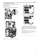
F-5-15
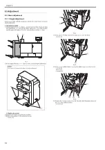
2) Lift the upper cover [1] in the arrow direction to remove the inner cover
(upper) [2].
- 4 screws [3]
F-5-16
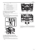
3) Loosen the 2 screws [2] on the latch base (front) [1].
4) If the value obtained at "checking adjustment value" is "+ (positive)",
move it in [A] direction and tighten the screws [2].
If the value obtained at "checking adjustment value" is "- (negative)",
move it in [B] direction and tighten the screws [2].
F-5-17
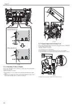
5) Loosen the 2 screws [2] on the latch base (rear) [1].
6) If the value obtained at "checking adjustment value" is "+ (positive)",
move it in [A] direction and tighten the screws [2].
If the value obtained at "checking adjustment value" is "- (negative)",
move it in [B] direction and tighten the screws [2].
F-5-18
7) Connect the finisher with the host machine.
8) Turn ON the power switch of the host machine then the finisher.
9) Check the adjustment value again.
If the adjustment value indicated on the LED is within the range, press
ENTER button to complete the adjustment mode.
If the adjustment value indicated on the LED is out of the range, execute
adjustment for the second time. Adjustment can be considered OK to
complete if the value gets closer to the adjustment range (estimated
value).
10) Put the DIP switch setting back and install the removed covers/parts.
5.3.1.3 Adjusting Sensor Light Intensity
0021-1704
Execute this adjustment in the case of the following:
- When installing the finisher
- When replacing a sensor
- When replacing EEPROM (IC107) on the finisher controller PCB
Following shows the operating procedure:
CAUTION:
Be careful not to drop the bearing [1] that is attached inside the knob.
[2]
[1]
[1]
[2]
[3]
[1]
CAUTION:
Perform adjustment so that the total of the shifting amount (scale) of the
latch base (front/rear) is within -2 to +2 mm.
CAUTION:
Perform adjustment so that the total of the shifting amount (scale) of the
latch base (front/rear) is within -2 to +2 mm.
[B]
[A]
[1]
[2]
[B]
[A]
[1]
[2]
Содержание Saddle Finisher-AF2
Страница 1: ...SERVICE MANUAL Saddle Finisher AF2 MARCH 6 2009...
Страница 2: ......
Страница 6: ......
Страница 12: ...Contents...
Страница 13: ...Chapter 1 Specifications...
Страница 14: ......
Страница 16: ......
Страница 22: ......
Страница 23: ...Chapter 2 Installation...
Страница 24: ......
Страница 26: ......
Страница 55: ...Chapter 3 Functions...
Страница 56: ......
Страница 58: ......
Страница 104: ...Chapter 3 3 46...
Страница 105: ...Chapter 4 Parts Replacement Procedure...
Страница 106: ......
Страница 110: ......
Страница 157: ...Chapter 4 4 47 F 4 213 3 2 1...
Страница 158: ......
Страница 159: ...Chapter 5 Maintenance...
Страница 160: ......
Страница 209: ...Chapter 5 5 47 F 5 221 SW382 SW381 SW383 ENTER SW384 SW385 DSP381 1...
Страница 217: ...Chapter 5 5 55 3 Door switch tool Front door switch ON tool number FY9 8006 No Name Description Composition Remarks...
Страница 218: ......
Страница 219: ...Appendix...
Страница 220: ......
Страница 221: ...General Timing Chart General Circuit Diagram Finisher Sorter DeliveryTray Saddle Finisher AF2...
Страница 222: ......
Страница 224: ......
Страница 225: ...Contents 1 General Circuit Diagram 1 Signal Names 1 General Circuit Diagram 9...
Страница 226: ......
Страница 243: ......
Страница 244: ......