background image

2-4

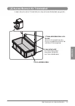
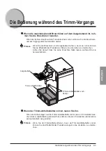
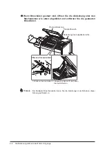
Die Bedienung während des Trimm-Vorgangs

 Wenn Broschüren gestaut sind, öffnen Sie die Abdeckung oder den 

Mechanismus wie unten abgebildet und entfernen Sie die gestauten 
Broschüren.

1

2

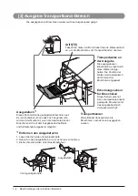
 Transportbereich

 Obere Abdeckung

1. Drücken Sie den Hebel. 2. Fassen Sie den Griff und heben 

Sie die Einheit an.

 Abdeckung des Ausgabebereichs

Öffnen der Transporteinheit

Hinweis


Bei häufigem Broschürenstau lesen Sie die Anleitungen zum Beheben dieser 
Störung auf Seite 3-4.

Содержание Perfect Binder B1

Страница 1: ...module brochure B1 Zwei Seiten Trimmer B1 Two Knife Booklet Trimmer B1 Cizalla de Cuadernillos de Doble Hoja B1 User s Guide Guide de I utilisateur Anwenderhandbuch Guida per l utente Gu a de usuario...

Страница 2: ...ENGLISH Structure of the Users Guide Chapter 1 Before You Begin Read here first Chapter 2 Operating Procedures Chapter 3 Troubleshooting Chapter 4 Appendix...

Страница 3: ......

Страница 4: ...the environmen tal specifications for the product Canon pursues a policy of continuing improvement in design and performance of the product Therefore the product design and specifications are subject...

Страница 5: ...seful supplementary information for operational proce dures Operating Safety Precautions WARNING When moving the machine be sure to turn off all of the power switches for the connected equip ment then...

Страница 6: ...ment generates uses and can radiate radio frequency energy and if not installed and used in accordance with the instruction manual may cause harmful interference to radio communications Operation of t...

Страница 7: ...tion 1 2 Section Descriptions 1 3 1 Two Knife Trim Section 1 3 2 Conveyor Section 1 4 3 Trim Ejecting Section 1 5 Section 2 Operating Procedures Trimmer Setup 2 2 Operation While Trimming 2 3 Section...

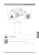
Страница 8: ...v ENGLISH Caution Label Locations Do not touch this part Otherwise you may be burned Keep your hands and fingers away from this area to prevent injury...

Страница 9: ...vi...

Страница 10: ...1 CHAPTER 1 1 Before You Begin Machine Description 1 2 Section Descriptions 1 3 1 Two Knife Trim Section 1 3 2 Conveyor Section 1 4 3 Trim Ejecting Section 1 5...

Страница 11: ...1 2 Machine Description Machine Description 1 2 3 1 Two Knife Trim Section See page 1 3 2 Conveyor Section See page 1 4 3 Trim Ejecting Section See page 1 5...

Страница 12: ...the conveyor section 1 2 Booklet Transport Unit TF2 If any booklets jam in the two knife trim section press the handle and lift up this mechanism to remove the jammed booklets Transport Belts These be...

Страница 13: ...y to match the booklet size Delivery Tray 1 This tray holds the stacked booklets It is removable When the tray is removed the conveyor full condition not detected and continuous oper ation is possible...

Страница 14: ...ng Section Trim is ejected into the trim box through this section Trim Full Sensor If trim stacks up between the sensor and the reflector a Trim Full error is indicated Trim Box Delivery Chute Trim is...

Страница 15: ...1 6 Section Descriptions...

Страница 16: ...2 CHAPTER 2 1 Operating Procedures Trimmer Setup 2 2 Operation While Trimming 2 3...

Страница 17: ...power switch on the saddle stitcher first then turn on the power switch on the host machine printer The trimmer will also be powered on because it is connected to the saddle stitcher See the operation...

Страница 18: ...an increase production efficiency without interrupting the operation Be careful not to drop a booklet while removing it Delivery Tray Trim Box Trim Full Sensor When the trim box is full empty it If th...

Страница 19: ...sm shown below and remove the jammed booklets 1 2 Transport Section Top Cover 1 Press the handle 2 Hold the handle and lift the unit Delivery Section Cover Opening the Transport Unit If the booklets j...

Страница 20: ...3 1 3 CHAPTER Troubleshooting This section describes some possible problems and suggests some solutions Error Messages 3 2 Service Call Error 3 2 Error Message Chart 3 3 Clearing Paper Jams 3 4...

Страница 21: ...reak the insulation which may result in fire or elec trical shock Service Call Error If the SERVICE CALL ERROR appears on the LCD of the host machine turn off the power switches on the saddle stitcher...

Страница 22: ...e jammed booklet Reposition the A and F2 transport unit and close the top cover 1 and the delivery section cover 2 to restart the printing A booklet jam has occurred in the two knife trim section Open...

Страница 23: ...See procedure 2 Procedure 1 Open the transport unit and check to see if there are any paper chips left on the booklet feed path See page 3 3 Procedure 2 The transport belts must be cleaned Contact yo...

Страница 24: ...4 CHAPTER 4 1 Appendix Specifications 4 2 Specifications 4 3 Index 4 4...

Страница 25: ...45 kg 319 lb Without conveyor section and delivery tray Installation Space with Host Machine Installation space differs depending on the connected host machine Refer to the Machine Dimension described...

Страница 26: ...145 kg 319 lb Without conveyor section and delivery tray Installation Space with Host Machine Installation space differs depending on the connected host machine Refer to the Machine Dimension describ...

Страница 27: ...elivery Tray 1 4 2 3 E Error Messages 3 2 H Handle 1 3 1 4 J Jam in Infeed Section 3 4 Jam in Trim Section 3 4 P Paper Jams 3 4 S Service Call Error 3 2 Specifications 4 2 T Top Cover 1 3 2 4 Transpor...

Страница 28: ...FRAN AIS Structure du Guide de l utilisateur Chapitre 1 Avant de commencer Lire cette section en priorit Chapitre 2 Proc dures d utilisation Chapitre 3 D pannage Chapitre 4 Annexe...

Страница 29: ......

Страница 30: ...iantes non conformes aux sp cifi cations Canon a pour politique d am liorer en continu les performances et la conception de ses produits Il est donc possible que l aspect et les sp cifications de ce p...

Страница 31: ...s en lien avec les proc dures d utilisation d crites Consignes de s curit AVERTISSEMENT Avant de d placer la machine veiller mettre tous les interrupteurs du p riph rique connect sur Arr t puis d bran...

Страница 32: ...ne 1 2 Description des zones 1 3 1 Zone de massicotage deux lames 1 3 2 Zone de convoyage 1 4 3 Zone d jection de r sidus de massicotage 1 5 CHAPITRE 2 Proc dures d utilisation Pr paration du massicot...

Страница 33: ...iv Emplacements des tiquettes de mise en garde Ne pas toucher cette partie Sinon on risquera de se br ler Maintenir les doigts et les mains loign s de cette zone pour viter les blessures...

Страница 34: ...1 CHAPITRE 1 1 Avant de commencer Description de la machine 1 2 Description des zones 1 3 1 Zone de massicotage deux lames 1 3 2 Zone de convoyage 1 4 3 Zone d jection de r sidus de massicotage 1 5...

Страница 35: ...1 2 Description de la machine Description de la machine 1 2 3 1 Zone de massicotage deux lames Voir page 1 3 2 Zone de convoyage Voir page 1 4 3 Zone d jection de r sidus de massicotage Voir page 1 5...

Страница 36: ...odule de transport des brochures TF2 En cas de bourrage dans la zone de massicotage deux lames appuyer sur la poign e et soulever le m canisme pour retirer les brochures bloqu es Courroies de transpor...

Страница 37: ...s Bac de sortie 1 Ce bac maintient les brochures empil es Il est amovible Lorsque le bac est retir le niveau plein du convoyeur n est pas d tect et un fonctionnement continu est possible Capteur de d...

Страница 38: ...age sont ject s dans le r ceptacle via cette zone D tecteur de r ceptacle plein Si des r sidus s empilent entre le d tecteur et le r flecteur une erreur indique que le r ceptacle est plein R ceptacle...

Страница 39: ...1 6 Description des zones...

Страница 40: ...2 CHAPITRE 2 1 Proc dures d utilisation Pr paration du massicot 2 2 Fonctionnement pendant le massicotage 2 3...

Страница 41: ...pteur du module d agrafage avec piq re cheval puis celui de la machine h te imprimante sur MARCHE Le massicot sera galement mis sous tension car il est connect au module d agrafage avec piq re cheval...

Страница 42: ...productivit sans interrompre le fonctionnement Faire attention ne pas faire tomber les brochures en les retirant Bac de sortie R ceptacle de r sidus D tecteur de r ceptacle plein Lorsque le r ceptacle...

Страница 43: ...ci dessous et retirer les brochures bloqu es 1 2 Zone de transport Capot sup rieur 1 Appuyer sur la poign e 2 Tenir la poign e et soulever le module Capot de la zone de sortie Ouverture du module de t...

Страница 44: ...3 CHAPITRE 3 1 D pannage Ce chapitre d crit les probl mes possibles et sugg re des solutions Messages d erreur 3 2 Erreur SAV 3 2 Tableau des messages d erreur 3 3 Elimination des bourrages papier 3 4...

Страница 45: ...e rompre l isolation Il y aurait alors danger d incendie ou d lectrocution Erreur SAV Si le message SERVICE CALL ERROR appara t sur l afficheur de la machine h te mettre les interrupteurs du module d...

Страница 46: ...de transport A et F2 puis fermer le capot sup rieur 1 et le capot de la zone de sortie 2 pour reprendre l impression Un bourrage s est produit dans la zone de massicotage deux lames Ouvrir le capot su...

Страница 47: ...r proc dure 2 Bourrage dans la zone de convoyeur Bourrages de morceaux de papier Voir proc dure 1 Les courroies de transport sont sales Voir proc dure 2 Proc dure 1 Ouvrir le module de transport et v...

Страница 48: ...4 CHAPITRE 4 1 Annexe Fiche technique 4 2 Fiche technique 4 2 Index 4 3...

Страница 49: ...e sortie Poids 145 kg 319 lb environ sans zone de convoyage ni bac de sortie Encombrement machine h te incluse L espace d installation varie en fonction de la machine h te con nect e Voir la section s...

Страница 50: ...e r ceptacle plein 1 5 2 3 E Erreur SAV 3 2 F Fiche technique 4 2 L Lames du massicot 1 3 Le convoyeur est plein 3 3 M Messages d erreur 3 2 Module de transport des brochures 1 3 P Poign e 1 3 1 4 Pr...

Страница 51: ...4 4...

Страница 52: ...DEUTSCH Aufbau des Anwenderhandbuchs Kapitel 1 Vor dem Start Bitte lesen Sie diesen Abschnitt zuerst Kapitel 2 Die Bedienung Kapitel 3 St rungsbeseitigung Kapitel 4 Anhang...

Страница 53: ......

Страница 54: ...lscher Verwendung oder Bedienung die nicht den Anleitungen entspricht Canon ist bestrebt st ndig Verbesserungen an Design und technischen Daten des Produkts vorzunehmen Daher bleiben Ver nderungen an...

Страница 55: ...ler Werte und ber Betriebsbedingungen Dieses Symbol kennzeichnet sinnvolle erg nzende Informationen f r die Bedie nung der Einheit Vorsichtsma nahmen f r sichere Bedienung WARNUNG Bevor Sie das System...

Страница 56: ...ungen nicht w hrend die Einheit arbeitet da die Einheit dann stoppen und ein Papierstau entstehen k nnte Verwenden Sie diese Einheit nur in einem B ro oder einem Gewerbebereich Verwenden Sie die Einhe...

Страница 57: ...nen Bereiche 1 3 1 Trimmbereich mit zwei Messern 1 3 2 Ausgabe Transportband Bereich 1 4 3 Auswurfbereich f r Trimmabfall 1 5 Section 2 Die Bedienung Das Einrichten des Trimmers 2 2 Die Bedienung w hr...

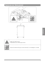
Страница 58: ...v DEUTSCH Positionen der Warnschilder Ber hren Sie dieses Teil nicht Andernfalls kann es zu Verbrennungen kommen Halten Sie Ihre H nde und Finger von diesem Bereich fern um Verletzungen zu vermeiden...

Страница 59: ...vi...

Страница 60: ...1 KAPITEL Vor dem Start Beschreibung der Einheit 1 2 Beschreibungen der einzelnen Bereiche 1 3 1 Trimmbereich mit zwei Messern 1 3 2 Ausgabe Transportband Bereich 1 4 3 Auswurfbereich f r Trimmabfall...

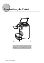
Страница 61: ...1 2 Beschreibung der Einheit Beschreibung der Einheit 1 2 3 1 Trimmbereich mit zwei Messern vgl Seite 1 3 2 Ausgabe Transportbereich vgl Seite 1 4 3 Ausgabebereich nach dem Trimmen vgl Seite 1 5...

Страница 62: ...ransportb nder Diese B nder transpor tieren die Brosch ren Trimm Messer Diese Messer schneiden einen glatten Rand an der oberen und der unteren Kante jeder Brosch re Griff Obere Abdeckung Brosch ren T...

Страница 63: ...ch nimmt die gestapelten Brosch ren auf Es ist abnehmbar Wenn das Fach abgenommen wird wird nicht erkannt wenn die maximale Anzahl Brosch ren sich auf dem Ausgabeband befindet und fortlaufende Ausgabe...

Страница 64: ...d der Trimmabfall in den entsprechenden Abfallbeh lter ausgeworfen Trimm Abfallbeh lter voll Sensor Wenn sich Trimmabfall zwischen Sensor und Reflektor gesammelt hat wird dieser Fehler angezeigt Trimm...

Страница 65: ...1 6 Beschreibungen der einzelnen Bereiche...

Страница 66: ...2 2 1 KAPITEL Die Bedienung Das Einrichten des Trimmers 2 2 Die Bedienung w hrend des Trimm Vorgangs 2 3...

Страница 67: ...halten Sie die Hefteinheit am Hauptschalter ein und dann die Haupteinheit Drucker an deren Hauptschalter Der Trimmer wird ebenfalls eingeschaltet weil er mit der Sattelheftungseinheit ver bunden ist R...

Страница 68: ...duktion erh hen ohne die Aktion zu unterbrechen Achten Sie darauf dass Sie keine Brosch re fallen lassen w hrend Sie sie herunternehmen Ausgabefach Trimm Abfallbeh lter voll Sensor Trimm Abfallbeh lte...

Страница 69: ...abgebildet und entfernen Sie die gestauten Brosch ren 1 2 Transportbereich Obere Abdeckung 1 Dr cken Sie den Hebel 2 Fassen Sie den Griff und heben Sie die Einheit an Abdeckung des Ausgabebereichs ff...

Страница 70: ...tigung In diesem Abschnitt finden Sie Erl uterungen zu Problemen die m glicherweise auftreten k nnen sowie Hinweise zu L sungen Fehlermeldungen 3 2 Serviceruf Fehler 3 2 Andere Fehler 3 3 Das Entferne...

Страница 71: ...der die Dr hte bzw ihre Isolierung besch digen So kann ein Feuer oder ein elektrischer Schlag verursacht werden Serviceruf Fehler Wenn die Meldung SERVICE CALL ERROR auf dem Display des Host angezeigt...

Страница 72: ...d schlie en Sie die obere Abdeckung 1 und die Abdeckung des Ausgabebereichs 2 um den Druckvorgang wieder zu starten Im Trimmbereich mit den zwei Messern ist ein Brosch renstau aufgetreten ffnen Sie di...

Страница 73: ...mutzt Vgl L sung 2 Papierstau im Transportband Bereich Papierschnipsel sind gestaut Vgl Ma nahmen 1 Transportb nder sind verschmutzt Vgl Ma nahmen 2 L sung 1 ffnen Sie die Transporteinheit und pr fen...

Страница 74: ...4 4 1 KAPITEL Anhang Technische Daten 4 2 Technische Daten 4 2 Index 4 3...

Страница 75: ...kg 319 lb ohne Transportbereich und Ausgabefach Platzbedarf zusammen mit dem Host System Der Platzbedarf richtet sich nach dem angeschlossenen Host System N here Informationen finden Sie unter Abmess...

Страница 76: ...B Brosch ren Transporteinheit 1 3 D Das Ausgabeband ist voll 3 3 Das Einrichten des Trimmers 2 2 Das Entfernen von gestautem Papier 3 4 F Fehlermeldungen 3 2 G Griff 1 3 1 4 O Obere Abdeckung 1 3 2 4...

Страница 77: ...4 4...

Страница 78: ...Struttura della Guida per l utente Capitolo 1 Prima di iniziare Prima di iniziare leggere questa parte Capitolo 2 Procedure di utilizzo Capitolo 3 Individuazione e soluzione dei problemi Capitolo 4 A...

Страница 79: ......

Страница 80: ...utilizzo in condizioni diverse da quelle indicate nelle specifiche del prodotto Canon aggiorna continuamente i propri prodotti per quanto riguarda progettazione e prestazioni Di conseg uenza il desig...

Страница 81: ...rante l utilizzo AVVERTENZA Quando occorre spostare la macchina portare sulla posizione di spento tutti gli interruttori delle apparecchiature collegate quindi scollegare il cavo di alimentazione e me...

Страница 82: ...iii ITALIANO ATTENZIONE Utilizzare la macchina solo in ambito commerciale o in un ufficio Non utilizzare la macchina in ambito industriale...

Страница 83: ...e 1 3 2 Sezione di convogliamento per la consegna 1 4 3 Sezione di espulsione dei residui di rifilatura 1 5 Section 2 Procedure di utilizzo Preparazione dell unit di rifilatura 2 2 Operazioni durante...

Страница 84: ...v ITALIANO Attenzione Posizioni delle etichette Non toccare questa parte Altrimenti potreste bruciarvi Tenere le mani e le dita lontano da questa area per evitare lesioni...

Страница 85: ...vi...

Страница 86: ...di iniziare Descrizione della macchina 1 2 Descrizione delle varie sezioni 1 3 1 Sezione di rifilatura con due lame 1 3 2 Sezione di convogliamento per la consegna 1 4 3 Sezione di espulsione dei resi...

Страница 87: ...a macchina Descrizione della macchina 1 2 3 1 Sezione di rifilatura con due lame vedere pag 1 3 2 Sezione di convogliamento per la consegna vedere pag 1 4 3 Sezione di espulsione dei residui di rifila...

Страница 88: ...nto 1 2 Gruppo di trasporto opuscoli TF2 Se gli opuscoli dovessero incepparsi nella sezione di rifilatura con due lame premere l impugnatura e sollevare questo meccanismo per rimuovere gli opuscoli in...

Страница 89: ...gli opuscoli Vassoio di consegna 1 In questo vassoio vengono depositati gli opuscoli consegnati Il vassoio rimovibile quando il vas soio viene rimosso non viene rilevato quando il convogliatore per la...

Страница 90: ...erso questa sezione Sensore contenitore residui di rifilatura pieno Se i residui di rifilatura si accumulano tra il sensore ed il riflettore viene indicato un errore che segnala che il contenitore dei...

Страница 91: ...1 6 Descrizione delle varie sezioni...

Страница 92: ...2 2 1 CAPITOLO Procedure di utilizzo Preparazione dell unit di rifilatura 2 2 Operazioni durante la rifilatura 2 3...

Страница 93: ...latura 1 Accendere prima il gruppo di pinzatura a sella quindi accendere la macchina stampante Viene alimentata anche l unit di rifilatura poich collegata al gruppo di pinzatura a sella Configurare la...

Страница 94: ...tenzione a non fare cadere gli opuscoli durante la rimozione Sensore conten itore dei residui di rifilatura pieno Vassoio di consegna Contenitore dei residui di rifilatura Vuotare il contenitore dei r...

Страница 95: ...imuovere gli opuscoli inceppati 1 2 Sezione di trasporto Pannello superiore 1 Premere l impugnatura 2 Tenendo l impugnatura sollevare il gruppo Pannello della sezione di consegna Apertura del gruppo d...

Страница 96: ...ente capitolo vengono descritti alcuni problemi che si possono verificare e viene indicato come risolverli Messaggi di errore 3 2 Errore che richiede l intervento dell assistenza 3 2 Tabella delle sit...

Страница 97: ...solamento potrebbe risultare compromesso e potrebbero verificarsi incendi o scosse elettriche Errore che richiede l intervento dell assistenza Se viene visualizzato SERVICE CALL ERROR sul display dell...

Страница 98: ...are il gruppo di trasporto A e F2 quindi chiudere il pannello superiore 1 ed il pan nello della sezione di consegna 2 per riprendere a stam pare Si inceppato un opuscolo nella sezione di rifilatura co...

Страница 99: ...hi vedere la Procedura 2 Inceppamento nella sezione di convogliamento Inceppamento dovuto a frammenti di carta vedere la Procedura 1 I nastri di trasporto sono sporchi vedere la Procedura 2 Procedura...

Страница 100: ...4 4 1 CAPITOLO Appendice Specifiche 4 2 Specifiche 4 2 Indice analitico 4 3...

Страница 101: ...1 040 H mm 21 1 8 x 30 3 8 x 41 senza sezione di convogliamento e vassoio di consegna Peso Circa 145 kg 319 lb senza sezione di convogliamento e vassoio di consegna Ingombro inclusa macchina L ingomb...

Страница 102: ...rifilatura 3 4 L Lame di rifilatura 1 3 M Maniglia 1 3 Messaggi di errore 3 2 N Nastri di trasporto 1 3 1 4 P Pannello della sezione di consegna 2 4 Pannello superiore 1 3 2 4 Preparazione dell unit d...

Страница 103: ...4 4 Indice analitico...

Страница 104: ...ESPA OL Estructura de la gu a de usuario Cap tulo 1 Antes de comenzar Lea esto lo primero Cap tulo 2 Procedimientos de operaci n Cap tulo 3 Soluci n de problemas Cap tulo 4 Ap ndice...

Страница 105: ......

Страница 106: ...del producto Canon sigue una pol tica de mejoras continuas en el dise o y el rendimiento del producto Por consiguiente el dise o y las especificaciones del producto pueden estar sometidos a cambios s...

Страница 107: ...Este s mbolo indica el intervalo de valores y condiciones de funcionamiento aceptables Nota Este s mbolo indica informaci n adicional para procedimientos de utilizaci n Precauciones de seguridad en la...

Страница 108: ...iii ESPA OL PRECAUCI N Use este equipo nicamente en entornos comerciales o de oficina No utilice el equipo en un entorno industrial...

Страница 109: ...ecci n de recorte de doble hoja 1 3 2 Secci n de la cinta transportadora 1 4 3 Secci n de expulsi n de recortes 1 5 Section 2 Procedimientos de operaci n Configuraci n de la cizalla 2 2 Utilizaci n de...

Страница 110: ...v ESPA OL Ubicaciones de las etiquetas de precauci n No toque esta parte De lo contrario se puede quemar Mantenga sus manos y dedos alejados de esta rea para evitar lesiones...

Страница 111: ...vi...

Страница 112: ...CAP TULO Antes de comenzar Descripci n del equipo 1 2 Descripci n de las secciones 1 3 1 Secci n de recorte de doble hoja 1 3 2 Secci n de la cinta transportadora 1 4 3 Secci n de expulsi n de recorte...

Страница 113: ...del equipo Descripci n del equipo 1 Secci n de recorte de doble hoja Consulte la p gina 1 3 2 Secci n de la cinta transportadora Consulte la p gina 1 4 3 Secci n de expulsi n de recortes Consulte la p...

Страница 114: ...1 2 Unidad de transporte de cuadernillos TF2 Si se produce un atasco de cuadernillos en la secci n de recorte de doble hoja presione el tirador suba este mecanismo para sacar los cuadernillos atascad...

Страница 115: ...al tama o de los cuadernillos Bandeja de salida 1 Esta bandeja almacena los cuadernillos apilados La bandeja se puede quitar Cuando esta bandeja no est colocada el estado de cinta transportadora llen...

Страница 116: ...a el dep sito de recortes a trav s de esta secci n Sensor de llenado de recortes Si se acumulan los recortes entre el sensor y el reflector aparecer indicado el error de llenado de recortes Dep sito d...

Страница 117: ...1 6 Descripci n de las secciones...

Страница 118: ...2 2 1 CAP TULO Procedimientos de operaci n Configuraci n de la cizalla 2 2 Utilizaci n de la cizalla 2 3...

Страница 119: ...nterruptor de alimentaci n de la grapadora de cuadernillos y a continuaci n encienda el interruptor de la m quina principal impresora La cizalla recibir alimentaci n al estar conectada a la grapadora...

Страница 120: ...n sin interrumpir el funcionamiento del equipo Tenga cuidado de que los cuadernillos no se caigan al retirarlos Bandeja de salida Dep sito de recortes Sensor de llenado de recortes Si se llena el dep...

Страница 121: ...los cuadernillos atascados 1 2 Secci n de transporte Tapa superior 1 Presione el tirador 2 Agarre el tirador y levante la unidad Tapa de la secci n de salida Apertura de la unidad de transporte Nota...

Страница 122: ...de problemas En esta secci n se describen determinados problemas potenciales y se sugieren algunas soluciones Mensajes de error 3 2 Error de aviso de servicio 3 2 Tabla de mensajes de error 3 3 Elimin...

Страница 123: ...ede ocasionar incendios o descargas el ctricas Error de aviso de servicio Si el mensaje SERVICE CALL ERROR aparece en la pantalla de la m quina principal apague los interruptores de alimentaci n de la...

Страница 124: ...transporte A y F2 y cierre la tapa superior 1 y la tapa de la secci n de salida 2 para reanudar la impresi n Se ha producido un atasco de cuadernil los en la secci n de recorte de doble hoja Abra la t...

Страница 125: ...o en la secci n de la cinta transportadora Atascos por restos de papel Consulte el procedimiento 1 Las cintas de transporte est n sucias Consulte el procedimiento 2 Procedimiento 1 Abra la unidad de t...

Страница 126: ...4 4 1 CAP TULO Ap ndice Especificaciones 4 2 Especificaciones 4 2 ndice alfab tico 4 3...

Страница 127: ...la cinta transportadora ni la bandeja de salida Peso Aproximadamente 145 kg 319 lb sin la secci n de la cinta transportadora ni la bandeja de salida Espacio de instalaci n con la m quina principal El...

Страница 128: ...s 1 5 2 3 E Error de aviso de servicio 3 2 Especificaciones 4 2 L La cinta transportadora est llena 3 3 M Mensajes de error 3 2 R Rodillos de transporte de salida 1 4 S Secci n de expulsi n de recorte...

Страница 129: ...4 4 ndice alfab tico...

Страница 130: ...1 2 3 4 JAPANESE...

Страница 131: ......

Страница 132: ...i JAPANESE B1...

Страница 133: ...ii 145kg...

Страница 134: ...iii JAPANESE i ii ii iv 1 1 2 1 3 1 1 3 2 1 4 3 1 5 2 2 2 2 3 3 3 2 3 2 3 3 3 4 4 4 2 4 3...

Страница 135: ...iv...

Страница 136: ...1 1 1 CHAPTER 1 2 1 3 1 1 3 2 1 4 3 1 5...

Страница 137: ...1 2 1 2 3 1 1 3 2 1 4 3 1 5...

Страница 138: ...1 3 JAPANESE 1 1 2 TF2...

Страница 139: ...1 4 2 TE 1 1 2...

Страница 140: ...1 5 JAPANESE 3...

Страница 141: ...1 6...

Страница 142: ...2 1 2 CHAPTER 2 2 2 3...

Страница 143: ...2 2 1 ON ON...

Страница 144: ...2 3 JAPANESE...

Страница 145: ...2 4 1 2 3 4...

Страница 146: ...3 1 3 CHAPTER 3 2 3 2 3 3 3 4...

Страница 147: ...3 2 OFF 10 ON OFF...

Страница 148: ...3 3 JAPANESE 2 1 3 A E F2 1 E B1 A F2 A F2 B1 F2 F2 B1 F2 E E F2 1...

Страница 149: ...3 4 E F2 1 2 1 2 1 E F2 2...

Страница 150: ...4 1 4 CHAPTER 4 2 4 3...

Страница 151: ...13 x 19 2 330 2 mm x 487 7 mm 12 x 18 11 x 17 LGL LTRR 12 60 x 17 72 320 mm x 450 mm SRA3 2 15 mm 190 mm 1 500 15 mm A4 80 g m2 750 4 30 A4 40 80 g m2 20mm 536 W x 770 D x 1 040 H mm 145 kg AC 100V 4...

Страница 152: ...4 3 JAPANESE 3 2 1 4 3 3 1 2 1 5 1 5 2 3 3 3 1 2 1 4 3 3 3 2 1 3 4 2 1 3 3 3 1 3 1 2 1 3 1 3 1 4 1 4 2 3 3 3 1 5 1 3 1 4...

Страница 153: ...4 4...

Страница 154: ...a CANON EUROPA N V Bovenkerkerweg 59 1185 XB Amstelveen The Netherlands See http www canon europe com for details on your regional dealer CANON AUSTRALIA PTY LTD Building A The Park Estate 5 Talavera...

Отзывы: