


MV750i E, MV730i E, MV700i E, MV700 E, MV690 E
TECHNICAL DESCRIPTION
17
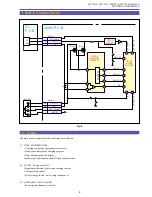
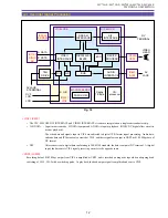
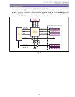
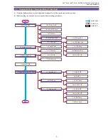
5-4 Personal Computer Connection Mode (USB)
In the card camera mode, an image signal produced in the camera section is sent to the memory card via the DIGIC DV. In the
personal computer connection mode, the USB terminal and the memory card are connected through the USB controller.
The FR MI-COM performs control of changeover between the card camera mode and the personal computer connection mode.
Fig. 14
Signal flow of (in)
Card camera mode
Signal flow of (in)
Personal computer
connection mode
IC1001
CCD
IC1101
SDRAM
IC1002
TG/CDS
AGC/AD
IC1103
DIGIC DV
MEMORY
CARD
USB
TERMINAL
Still Picture
Signal
Processing
FR
MI-COM
USB
CONTROLER
Содержание MV750i E
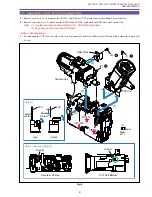
Страница 12: ...MV750i E MV730i E MV700i E MV700 E MV690 E GENERAL DESCRIPTION OF PRODUCT 10 External View Fig 1 ...
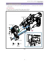
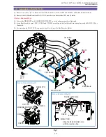
Страница 133: ...MV750i E MV730i E MV700i E MV700 E MV690 E DISASSEMBLING 39 Right Cover Unit LCD Unit LCD HINGE Unit Rear Cover Unit ...
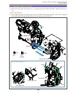
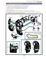
Страница 179: ...8 MV750i E MV730i E MV700i E MV700 E MV690 E PARTS LIST Right Cover Unit Section 1 1 2 7 5 10 10 11 8 9 6 4 A A 5 3 2 ...
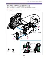
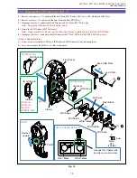
Страница 193: ...22 MV750i E MV730i E MV700i E MV700 E MV690 E PARTS LIST Lens Unit Section 1 1 2 3 1 1 1 2 ...
Страница 195: ...24 DMC III PARTS LIST 1 10 3 9 5 7 8 6 4 2 3 3 Mechanical Chassis Section 1 ...
Страница 197: ...26 DMC III PARTS LIST 1 2 3 4 5 6 7 8 6 1 9 10 13 11 12 Mechanical Chassis Section 2 ...
Страница 199: ...28 DMC III PARTS LIST 2 2 2 2 2 3 3 8 9 2 10 11 12 13 4 6 14 7 5 1 Mechanical Chassis Section 3 ...
Страница 201: ...30 DMC III PARTS LIST 1 3 4 5 8 9 6 10 7 2 11 Mechanical Chassis Section 4 ...