


MV750i E, MV730i E, MV700i E, MV700 E, MV690 E
DISASSEMBLING
35
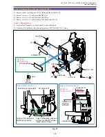
1-29 Disassembly of Camera Unit - 2
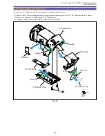
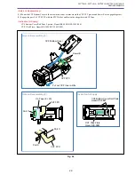
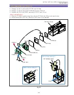
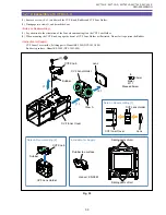
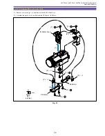
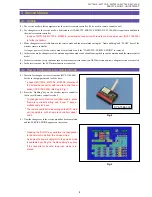
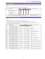
(1) Remove two screws (i
×
2), and detach the CCD P.C.B., CCD Ass’y, Rubber and IR Filter.
Note : To be manufactured using conventional-type Rubber material for two months after the start of mass-produc-
tion. Thereafter, new-type Rubber material is to be used.
For service Rubber parts, new-type Rubber material (DA3-1028-000) shall be used.
(2) Unsolder the part A, and detach the CCD Ass’y from the CCD P.C.B.
<Notes on Reassembling>
(1) Carry out soldering on the CCD P.C.B. at a status where the CCD Ass’y and CCD P.C.B. are fastened by two screws (i
×
2).
Fig. 32
i
5.5mm
Metal
M1.7
(self tap)
Face thick
side toward
CCD side
IR Filter
Lens
Part A
CCD
CCD P.C.B.
(2)
(1)
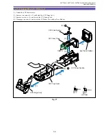
IR Filter
Lens Unit
Rubber
(NEW)
Rubber
(OLD)
CCD Ass'y
CCD P.C.B.
(2)
(1) - i
Содержание MV750i E
Страница 12: ...MV750i E MV730i E MV700i E MV700 E MV690 E GENERAL DESCRIPTION OF PRODUCT 10 External View Fig 1 ...
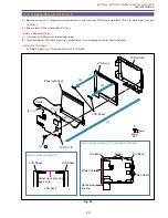
Страница 133: ...MV750i E MV730i E MV700i E MV700 E MV690 E DISASSEMBLING 39 Right Cover Unit LCD Unit LCD HINGE Unit Rear Cover Unit ...
Страница 179: ...8 MV750i E MV730i E MV700i E MV700 E MV690 E PARTS LIST Right Cover Unit Section 1 1 2 7 5 10 10 11 8 9 6 4 A A 5 3 2 ...
Страница 193: ...22 MV750i E MV730i E MV700i E MV700 E MV690 E PARTS LIST Lens Unit Section 1 1 2 3 1 1 1 2 ...
Страница 195: ...24 DMC III PARTS LIST 1 10 3 9 5 7 8 6 4 2 3 3 Mechanical Chassis Section 1 ...
Страница 197: ...26 DMC III PARTS LIST 1 2 3 4 5 6 7 8 6 1 9 10 13 11 12 Mechanical Chassis Section 2 ...
Страница 199: ...28 DMC III PARTS LIST 2 2 2 2 2 3 3 8 9 2 10 11 12 13 4 6 14 7 5 1 Mechanical Chassis Section 3 ...
Страница 201: ...30 DMC III PARTS LIST 1 3 4 5 8 9 6 10 7 2 11 Mechanical Chassis Section 4 ...