MV750i E, MV730i E, MV700i E, MV700 E, MV690 E
GENERAL DESCRIPTION OF PRODUCT
26
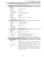
6-12-7 File transfer (MV750i E, MV730i E only)
a. USB file transfer
Still images (JPEG files) and motion video (Motion JPEG files) recorded on memory cards can
be uploaded to a PC and still images (JPEG files) on the PC can be downloaded to memory cards
in the camcorder by connecting the included IFC-300PCU interface cable between a USB port
on the PC and the USB port of the camcorder.
b. DV file transfer
Still images (JPEG files) and motion video (Motion JPEG files) recorded on memory cards can
be uploaded to a PC and still images (JPEG files) and motion video (Motion JPEG files) on the
PC can be downloaded to memory cards in the camcorder by connecting a CV-150F (or CV-
250F) DV cable between an IEEE1394 port on the PC and the DV terminal of the camcorder.
6-12-8 Analog / Digital conversion
Converts analog AV signals input to the AV terminal into digital DV signals in real-time and
outputs the digital DV signals from the DV terminal.
When an 8 mm video player or VHS video player is connected with the camcorder using an AV
cable, and the camcorder is connected to a PC using a DV cable, playback images can be trans-
ferred from the 8 mm tape or VHS tape to the PC. (Under the VCR settings on the VCR menu
screen, set AV input
⇒
DV output to ON.)
6-12-9 Playback zoom
If the zoom lever is flipped to the tele side during image playback from the tape or card (MV750i
E, MV730i E only, except for motion video), the image being played back can be enlarged to 5
times its size. When the zoom lever is flipped to the wide side, the enlarged image is returned to
its original size.
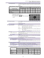
Position of the enlarged section during enlarged screen view can be changed by SET button. (On
the LCD monitor, a frame is displayed to show the zoom-in area, and the direction in which the
area can be moved by the SET button is indicated by / .) Toggling between the up/down
and left/right movement direction settings is performed by pressing the SET button. (“Left /
right” is the default setting when the mode is transferred to zoom-in.)
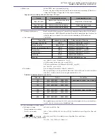
6-12-10 Battery charging function
When the CA-570 Canon compact power adapter is connected, the battery pack installed in the
battery pack compartment can be charged. (During charging, the charge lamp flashes (one flash
with a charge level of 0% to 50% or two flashes with a charge level of 50% or more) or it lights
(when the charging is complete with a charge level of 95% or more)).
Charging time
BP-508 : approx. 110 minutes, BP-511 / 512 : approx. 120 minutes,
(when power switch is at OFF) BP-514 : approx. 150 minutes, BP-522 : approx. 210 minutes, BP-535 : approx. 310 minutes.
6-12-11 Simultaneous still image
When the photo button is operated while motion video is recorded on a tape, still images
recording
(image size : 640
×
480, image quality : Super fine, Fine or Normal selected) can be recorded on
the memory card.
6-12-12 Accessory shoe
Supported
6-12-13 Recording lamp
None
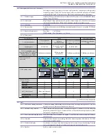
6-13 Terminal
6-13-1 DV terminal
Special 4-pin (IEEE1394 compatible) ; input and output (output only on MV700 E, MV690 E.)
6-13-2 S-Video terminal(MV750i E only)
4-pin mini-DIN ; input and output
6-13-3 AV (Audio / Video) terminal
φ
3.5 mm 4-pole pin jack (yellow) ; input / output (output only on MV700 E, MV690 E.)
Also serves as headphone terminal
6-13-4 External microphone input
None
terminal
6-13-5 Headphone terminal
φ
3.5 mm stereo mini-jack (also serves as AV terminal)
6-13-6 Memory card connection
Special multi-pin (MV750i E, MV730i E only)
terminal
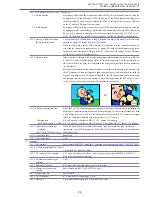
6-13-7 Battery terminal
Special 3-pin
6-13-8 DC IN terminal
φ
3.4 mm jack (for connecting CA-570)
6-13-9 USB port
5-pin (mini-B Receptacle ; MV750i E, MV730i E only)
(PAL models excluded)
(MV750i E, MV730i E only)
Содержание MV750i E
Страница 12: ...MV750i E MV730i E MV700i E MV700 E MV690 E GENERAL DESCRIPTION OF PRODUCT 10 External View Fig 1 ...
Страница 133: ...MV750i E MV730i E MV700i E MV700 E MV690 E DISASSEMBLING 39 Right Cover Unit LCD Unit LCD HINGE Unit Rear Cover Unit ...
Страница 179: ...8 MV750i E MV730i E MV700i E MV700 E MV690 E PARTS LIST Right Cover Unit Section 1 1 2 7 5 10 10 11 8 9 6 4 A A 5 3 2 ...
Страница 193: ...22 MV750i E MV730i E MV700i E MV700 E MV690 E PARTS LIST Lens Unit Section 1 1 2 3 1 1 1 2 ...
Страница 195: ...24 DMC III PARTS LIST 1 10 3 9 5 7 8 6 4 2 3 3 Mechanical Chassis Section 1 ...
Страница 197: ...26 DMC III PARTS LIST 1 2 3 4 5 6 7 8 6 1 9 10 13 11 12 Mechanical Chassis Section 2 ...
Страница 199: ...28 DMC III PARTS LIST 2 2 2 2 2 3 3 8 9 2 10 11 12 13 4 6 14 7 5 1 Mechanical Chassis Section 3 ...
Страница 201: ...30 DMC III PARTS LIST 1 3 4 5 8 9 6 10 7 2 11 Mechanical Chassis Section 4 ...


