MV750i E, MV730i E, MV700i E, MV700 E, MV690 E
SERVICE HINTS
5
2. Trouble Shooting
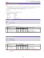
To detect the failure part for repair, if any, use the following hints and check points.
2-1 Power Supply
<Hints>
When the power source is attached, the unit enters the standby mode in the following sequences.
Main power is connected.
→
UNREG is supplied to the MAIN P.C.B.
→
MODE MI-COM starts up.
→
MODE MI-COM outputs VCR
ON “H” signal.
→
PWM driver starts up and turns on each power supply.
→
Establishes communication with the FR MI-COM.
→
FR
MI-COM initializes recorder mechanical chassis.
→
After initialized, the MODE MI-COM is brought into the standby status with the
VCR ON changed to VCR Low.
After that, the power supply is turned ON by the following procedures.
Power supply mode switch operation
→
After MODE MI-COM is accepted, VCR ON “H” is output.
→
The PWM driver is started to
turn on various power supplies.
→
The FR MI-COM is started to control the system.
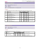
<Check Points>
1)
Key Inputs
Check the key inputs at Powe r Switch in the SERVICE mode.
2)
Check of microcomputer-to-microcomputer communication
If the microcomputer-to-microcomputer communication line is normal, the version number of each microcomputer can be indi-
cated in the service mode. Otherwise, the communication line or microcomputer may be faulty.
3)
Error in Mechanism (“SERVICE MODE · ADJUSTMENT” P. 8)
If any error is occurred by mechanism trouble at initializing, the error can be detected.
At this state, the power can be turned on, but the unit enters “ERROR STOP” state. In this case, check the error data in the
SERVICE mode.
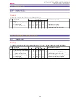
4)
VCR ON “H”, CAM ON “H” (control signal from MODE MI-COM) Outputs
Check the output of control signal by the LANC remote controller.
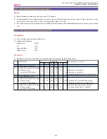
5)
Fuses on the POWER SUPPLY P.C.B.
Check the continuity of the fuses FU3201, 3202, 3203 and 1801 on the MAIN P.C.B. In case of NG, replace the fuse and check the
power consumption.
6)
Replace the MAIN P.C.B. with a service part and check the operation.
Содержание MV750i E
Страница 12: ...MV750i E MV730i E MV700i E MV700 E MV690 E GENERAL DESCRIPTION OF PRODUCT 10 External View Fig 1 ...
Страница 133: ...MV750i E MV730i E MV700i E MV700 E MV690 E DISASSEMBLING 39 Right Cover Unit LCD Unit LCD HINGE Unit Rear Cover Unit ...
Страница 179: ...8 MV750i E MV730i E MV700i E MV700 E MV690 E PARTS LIST Right Cover Unit Section 1 1 2 7 5 10 10 11 8 9 6 4 A A 5 3 2 ...
Страница 193: ...22 MV750i E MV730i E MV700i E MV700 E MV690 E PARTS LIST Lens Unit Section 1 1 2 3 1 1 1 2 ...
Страница 195: ...24 DMC III PARTS LIST 1 10 3 9 5 7 8 6 4 2 3 3 Mechanical Chassis Section 1 ...
Страница 197: ...26 DMC III PARTS LIST 1 2 3 4 5 6 7 8 6 1 9 10 13 11 12 Mechanical Chassis Section 2 ...
Страница 199: ...28 DMC III PARTS LIST 2 2 2 2 2 3 3 8 9 2 10 11 12 13 4 6 14 7 5 1 Mechanical Chassis Section 3 ...
Страница 201: ...30 DMC III PARTS LIST 1 3 4 5 8 9 6 10 7 2 11 Mechanical Chassis Section 4 ...

