


MV750i E, MV730i E, MV700i E, MV700 E, MV690 E
DISASSEMBLING
26
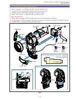
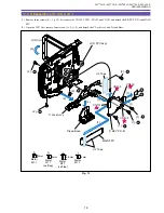
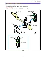
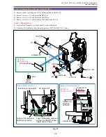
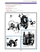
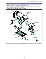
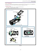
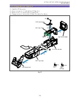
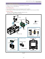
1-22 Disassembly of Rear Cover Unit - 1
(1) Remove the SD Card Sheet and CN101, and detach the LI-MAIN FPC.
(2) Remove a screw (c
×
1), and detach the DC P.C.B.
(3) Remove a screw (c
×
1), and detach the GND Plate.
(4) Remove a screw (c
×
1), and detach the LED Guide and LI P.C.B.
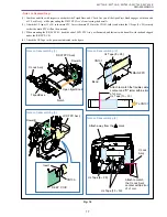
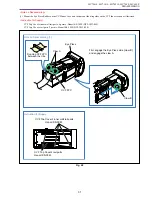
<Note on Reassembling>
(1) Treat the Batt Terminal Ass’y Cable and DC Cable as illustrated.
(2) Attach the SD Card Sheet at the illustrated position. (MV750i E, MV730i E only)
Fig. 23
Metal
M1.7
(self tap)
4.5mm
c
LI-MAIN FPC
LI-MAIN FPC
LED Guide
DC Cable (3P)
Batt Terminal Cable (6P)
GND Plate
LI P.C.B.
SD Card Sheet
SD Card Sheet
(3)
(1)
(1)
(2)
(4)
CN101
(3) - c
(4) - c
Guideline for
attaching
±
0.5 mm
Guideline for
attaching
±
0.5 mm
MV750i E,
MV730i E Only
MV750i E,
MV730i E Only
Note on Reassembling (1)
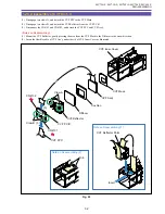
Note on Reassembling (2)
Take out the red wire of
Batt Terminal Cable.
Take out the black, gray and
white wires of Batt Terminal
Cable, and DC Cable.
DC P.C.B.
(2) - c
(4)
Содержание MV750i E
Страница 12: ...MV750i E MV730i E MV700i E MV700 E MV690 E GENERAL DESCRIPTION OF PRODUCT 10 External View Fig 1 ...
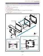
Страница 133: ...MV750i E MV730i E MV700i E MV700 E MV690 E DISASSEMBLING 39 Right Cover Unit LCD Unit LCD HINGE Unit Rear Cover Unit ...
Страница 179: ...8 MV750i E MV730i E MV700i E MV700 E MV690 E PARTS LIST Right Cover Unit Section 1 1 2 7 5 10 10 11 8 9 6 4 A A 5 3 2 ...
Страница 193: ...22 MV750i E MV730i E MV700i E MV700 E MV690 E PARTS LIST Lens Unit Section 1 1 2 3 1 1 1 2 ...
Страница 195: ...24 DMC III PARTS LIST 1 10 3 9 5 7 8 6 4 2 3 3 Mechanical Chassis Section 1 ...
Страница 197: ...26 DMC III PARTS LIST 1 2 3 4 5 6 7 8 6 1 9 10 13 11 12 Mechanical Chassis Section 2 ...
Страница 199: ...28 DMC III PARTS LIST 2 2 2 2 2 3 3 8 9 2 10 11 12 13 4 6 14 7 5 1 Mechanical Chassis Section 3 ...
Страница 201: ...30 DMC III PARTS LIST 1 3 4 5 8 9 6 10 7 2 11 Mechanical Chassis Section 4 ...