

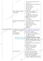
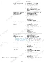


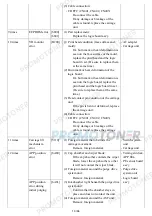


opens and closes properly.
(2) Smearing or scratches on the LF / EJ slit
film:
Clean the LF / EJ slit film using lint-
free paper.
(3) Foreign material in the LF drive:
Remove foreign material.
(4) Cable connection:
- LF encoder cable
- PE sensor cable
- Paper feed relay harness ass'y
- Paper feed motor harness ass'y
Re-connect the cables.
If any damage or breakage of the
cable is found, replace the cable.
(5) LF lock arm spring:
Attach the spring properly.
- Timing sensor
unit
- Paper feed roller
unit
- Logic board
ass'y
- Paper feed
motor
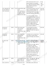
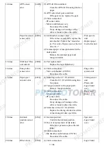
4 times
Purge cam
sensor error
[5C00]
(1) Foreign material around the purge drive
system unit:
Remove foreign material.
(2) Cable connection:
- Valve cam harness (CN700)
Re-connect the cable.
(3) Strange sound at power-on:
Replace the purge drive system unit.
- Purge drive
system unit
- Logic board
ass'y
5 times
ASF (cam)
sensor error
[5700]
(1) Cable connection:
- PE sensor cable
Re-connect the cable.
If any damage or breakage of the
cable is found, replace the cable.
- ASF unit
- PE sensor board
ass'y
- Logic board
ass'y
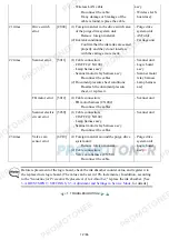
6 times
Internal
temperature
error
[5400]
(1) Cable connection:
- Ink absorber multi harness (CN701)
Re-connect the cable.
If any damage or breakage of the
cable is found, replace the spur unit.
- Spur unit
- Logic board
ass'y
- Print head
7 times
Ink absorber
full
[5B00]
[5B01]
(1) Ink absorber condition:
Replace the ink absorber, and reset
the ink absorber counter value in the
EEPROM.
8 times
Print head
temperature rise
error
[5200]
(1) Print head condition (face surface and
mold):
If a burn mark or heat deformation is
seen on the face surface or the mold,
replace the print head.
(2) Head contact pin condition of the carriage
unit:
If the pin is bent or deformed, replace
the carriage unit.
- Print head
- Logic board
ass'y
- Carriage unit
9 / 66
Содержание MG6110
Страница 24: ...5 Remove the main case no screws 20 66...
Страница 27: ...In reassembling attach the new protection sheet as it is over the remaining portions of the sheet 23 66...
Страница 36: ...3 Attach the cassette feed guide 4 Install the cassette feed roller unit 32 66...
Страница 44: ...4 Slowly lift the print unit to separate it from the bottom case 40 66...
Страница 58: ...54 66...
Страница 63: ...4 2 Integrated Inspection Pattern Print Print sample 59 66...
Страница 64: ...4 3 Ink Absorber Counter Value Print Print sample 4 VERIFICATION AFTER REPAIR 60 66...
Страница 68: ...64 66...