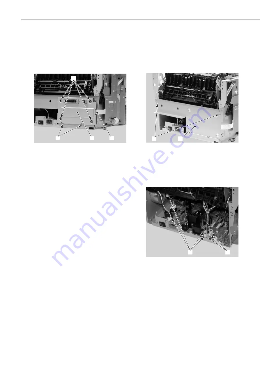
B. Interface PCB Unit
1) Remove the rear cover unit and left
cover unit.
2) Disconnect the flat cable and remove
the two screws with washers and four
screws. Remove the interface PCB unit.
➀
Flat cable
➁
Screws with washers
➂
Screw
➃
Interface PCB unit
Figure 3-7-2
C. Engine Controller Unit
1) Remove the rear cover unit, right cover,
and left cover unit.
2) Remove the interface PCB unit.
3) Remove the two screws and the PCB
fixing plate.
➀
Screws
➁
PCB fixing plate
Figure 3-7-3
4) Disconnect the seven connectors.
➀
Connectors
Figure 3-7-4
CHAPTER 3
3 - 23
➀
➃
➁
➂
➁
➀
➀
➀
Содержание LASER SHOT LBP-1210
Страница 8: ......
Страница 84: ...1 76 CHAPTER 1 ...
Страница 86: ......
Страница 129: ...This page intentionally left blank CHAPTER 2 2 43 ...
Страница 134: ...CHAPTER 2 2 48 ...
Страница 136: ......
Страница 142: ...4 Unhook the two left claws and remove the front guide unit Left claws Front guide unit Figure 3 2 14 CHAPTER 3 3 6 ...
Страница 164: ......
Страница 191: ...APPENDIX I GENERAL TIMING CHART A 1 II GENERAL CIRCUIT DIAGRAM A 2 III LIST OF SIGNALS A 3 IV MESSAGES TABLE A 5 ...
Страница 192: ......
Страница 202: ...The printing paper contains 70 waste paper PRINTED IN JAPAN IMPRIME AU JAPON CANON INC ...


