


Chapter 13
13-7
13.2
Scanning System
13.2.1
After Replacement
of the CIS
0007-9838
iR2270 / iR2870 / iR3570 / iR4570
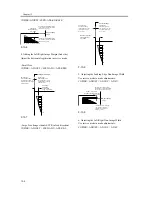
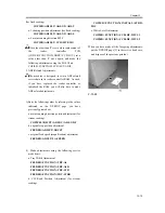
Be sure to enter the value indicated on the CIS label
attached to the contact image sensor (CIS) using the
following service mode item:
COPIER>ADJUST>CCD>MTF-MG
(main scanning direction MTR correction value)
F-13-21
Be sure also to update the value indicated on the
service label found behind the left cover of the reader
unit so that it is identical to the value indicated on the
CIS label.
Reference:
At time of shipment from the factory, no CIS label is
attached.
13.2.2
After Replacing the
Reader Controller PCB or
Initializing the RAM
0007-9839
iR2270 / iR2870 / iR3570 / iR4570
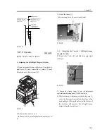
- Before replacing the reader controller PCB, be
sure to print out the latest P-PRINT page.
<if you are executing RAM initialization for the
reader controller without replacing the PCB>
- Using the SST, upload the backup data of the reader
controller, and download it after initializing the RAM
so that you need not perform the following:
1. Reader Unit-Related Adjustments
1) Using the SST, download the latest system
software (R-CON).
2) Make the following selections in service mode:
COPIER>FUNCTION>LEARN>R-CON. Then,
press the OK key to initialize the RAM; thereafter,
turn off and then on the main power.
3) Enter the following values in service mode:
a. values indicated on the service label (found
behind the left cover of the reader unit)
a-1. CIS read position adjustment (for fixed reading)
COPIER>ADJUST>ADJ-XY>ADJ-X
a-2. main scanning direction position adjustment
(for fixed reading)
COPIER>ADJUST>ADJ-XY>ADJ-Y
a-3. shading position adjustment (for fixed reading)
COPIER>ADJUST>ADJ-XY>ADJ-S
a-4. main scanning direction MTF
COPIER>ADJUST>CCD>MTF-MG
If a value other than '0' is set before replacement of
the reader controller PCB
(COPIER>FUNCTION>BODY>CCD-LUT), set a
value other than '0' once again, and make the
following adjustments using the D-10 Chart.
COPIER>FUNCTION>CCD>LUT-ADJ2
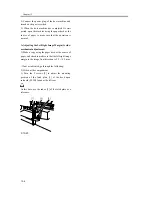
2. ADF-Related Adjustments
The machine is designed to retain ADF-related
X X
M T F - M G
Содержание iR4570 Series
Страница 2: ...Download Free Service Manual And Resetter Printer at http printer1 blogspot com ...
Страница 6: ...Download Free Service Manual And Resetter Printer at http printer1 blogspot com ...
Страница 27: ...Chapter 1 Introduction Download Free Service Manual And Resetter Printer at http printer1 blogspot com ...
Страница 28: ...Download Free Service Manual And Resetter Printer at http printer1 blogspot com ...
Страница 81: ...Chapter 2 Installation ...
Страница 82: ......
Страница 84: ......
Страница 106: ...system setup network Ethernet driver setup auto detect ...
Страница 126: ...F 2 94 3 2 3 1 ...
Страница 127: ...Chapter 3 Basic Operation ...
Страница 128: ......
Страница 130: ......
Страница 136: ......
Страница 137: ...Chapter 4 Main Controller ...
Страница 138: ......
Страница 140: ......
Страница 164: ......
Страница 165: ...Chapter 5 Original Exposure System ...
Страница 166: ......
Страница 213: ...Chapter 6 Laser Exposure ...
Страница 214: ......
Страница 216: ......
Страница 221: ...P ACC Motor acceleration signal P DEC Motor deceleration signal BD BD output level single Single Description ...
Страница 230: ......
Страница 231: ...Chapter 7 Image Formation ...
Страница 232: ......
Страница 236: ......
Страница 249: ...F 7 13 1 2 3 4 ...
Страница 308: ......
Страница 309: ...Chapter 8 Pickup Feeding System ...
Страница 310: ......
Страница 316: ......
Страница 379: ...Chapter 8 8 63 An image is formed for the 1st side of the 5th sheet F 8 85 The 5th sheet is delivered 4 1 2 3 5 ...
Страница 464: ......
Страница 465: ...Chapter 9 Fixing System ...
Страница 466: ......
Страница 500: ...Chapter 9 9 32 F 9 107 3 Disconnect the connector 1 and detach the fixing film sensor 2 F 9 108 ...
Страница 501: ...Chapter 10 External and Controls ...
Страница 502: ......
Страница 506: ......
Страница 564: ......
Страница 565: ...Chapter 11 MEAP ...
Страница 566: ......
Страница 567: ...Contents Contents 11 1 Overview 11 1 11 2 MEAP Counter 11 2 11 3 Construction of the MEAP Platform 11 4 ...
Страница 568: ......
Страница 573: ...Chapter 12 Maintenance and Inspection ...
Страница 574: ......
Страница 576: ......
Страница 612: ......
Страница 613: ...Chapter 13 Standards and Adjustments ...
Страница 614: ......
Страница 616: ......
Страница 635: ...Chapter 14 Correcting Faulty Images ...
Страница 636: ......
Страница 675: ...T 14 22 Notation Description VR201 for factory use ...
Страница 676: ......
Страница 677: ...Chapter 15 Self Diagnosis ...
Страница 678: ......
Страница 680: ......
Страница 757: ...Chapter 16 Service Mode ...
Страница 758: ......
Страница 760: ...Contents 16 8 1 COPIER 16 102 16 8 1 1 Copier List 16 102 ...
Страница 869: ...Chapter 17 Service Tools ...
Страница 870: ......
Страница 871: ...Contents Contents 17 1 Special Tools 17 1 17 2 Oils and Solvents 17 2 ...
Страница 872: ......
Страница 875: ...Oct 8 2004 ...
Страница 876: ......


