


Chapter 5
5-31
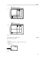
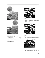
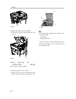
F-5-47
5.4.2.7
After Replacing the
Reader Controller PCB or
After Initializing the RAM
0007-0746
iR2270 / iR2870 / iR3570 / iR4570
- Before replacing the reader controller PCB, be sure
to generate the latest P-PRINT printout.
<if you are initializing the RAM of the reader
controller without replacing the PCB>
- Using the SST, upload the reader controller backup
data; after initializing the RAM, download the data,
thus eliminating the need for the following
adjustment.
1. Reader Unit-Related Adjustment
1) Using the SST, download the latest system
software (R-CON).
2) Make the following selections in service mode:
COPIER>FUNCTION>CLEAR>R-CON; then,
press the OK key to initialize the RAM. Thereafter,
turn off and then on the main power.
3) Enter the appropriate values using the following
service mode items:
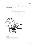
a. service label (behind reader unit left cover)
values
a-1. CIS read position adjustment (fixed reading)
COPIER>ADJUST>ADJ-XY>ADJ-X
a-2. main scanning direction position adjustment
(fixed reading)
COPIER>ADJUST>ADJ-XY>ADJ-Y
a-3. shading position adjustment (fixed reading)
COPIER>ADJUST>ADJ-XY>ADJ-S
a-4. main/sub scanning direction MTF value
COPIER>ADJUST>CCD>MTF-MG
If the value of the following was not 0 before the
replacement of the reader controller PCB:
COPIER>OPTION>BODY>CCD-LUT.
Set a value other than '0' once again, and make the
following adjustments using the D-10 Chart.
COPIER>FUNCTION>CCD>LUT-ADJ2
2. ADF-Related Adjustment
The machine keeps ADF-related service mode data in
the RAM of the reader controller; as such, you will
have to make the appropriate adjustments if you
have replaced the reader controller or initialized the
RAM.
1) Enter the values indicated in the P-PRINT printout
you have previously generated for the following:
a. main scanning direction position adjustment
(stream reading)
COPIER>ADJSUT>ADJ-XY>ADJ-Y-DF
b. original stop position adjustment
FEEDER>ADJSUT>DOCST
c. original feed speed (magnification) adjustment
FEEDER>ADUST>LA-SPEED
2) Make adjustments using the following items:
a. tray width adjustment
FEEDER>FUNCTION>TRY-A4
FEEDER>FUNCTION>TRY-A5R
FEEDER>FUNCTION>TRY-LTR
FEEDER>FUNCTION>TRY-LTRR
b. CIS read position adjustment (stream reading)
[1]
[2]
Содержание iR4570 Series
Страница 2: ...Download Free Service Manual And Resetter Printer at http printer1 blogspot com ...
Страница 6: ...Download Free Service Manual And Resetter Printer at http printer1 blogspot com ...
Страница 27: ...Chapter 1 Introduction Download Free Service Manual And Resetter Printer at http printer1 blogspot com ...
Страница 28: ...Download Free Service Manual And Resetter Printer at http printer1 blogspot com ...
Страница 81: ...Chapter 2 Installation ...
Страница 82: ......
Страница 84: ......
Страница 106: ...system setup network Ethernet driver setup auto detect ...
Страница 126: ...F 2 94 3 2 3 1 ...
Страница 127: ...Chapter 3 Basic Operation ...
Страница 128: ......
Страница 130: ......
Страница 136: ......
Страница 137: ...Chapter 4 Main Controller ...
Страница 138: ......
Страница 140: ......
Страница 164: ......
Страница 165: ...Chapter 5 Original Exposure System ...
Страница 166: ......
Страница 213: ...Chapter 6 Laser Exposure ...
Страница 214: ......
Страница 216: ......
Страница 221: ...P ACC Motor acceleration signal P DEC Motor deceleration signal BD BD output level single Single Description ...
Страница 230: ......
Страница 231: ...Chapter 7 Image Formation ...
Страница 232: ......
Страница 236: ......
Страница 249: ...F 7 13 1 2 3 4 ...
Страница 308: ......
Страница 309: ...Chapter 8 Pickup Feeding System ...
Страница 310: ......
Страница 316: ......
Страница 379: ...Chapter 8 8 63 An image is formed for the 1st side of the 5th sheet F 8 85 The 5th sheet is delivered 4 1 2 3 5 ...
Страница 464: ......
Страница 465: ...Chapter 9 Fixing System ...
Страница 466: ......
Страница 500: ...Chapter 9 9 32 F 9 107 3 Disconnect the connector 1 and detach the fixing film sensor 2 F 9 108 ...
Страница 501: ...Chapter 10 External and Controls ...
Страница 502: ......
Страница 506: ......
Страница 564: ......
Страница 565: ...Chapter 11 MEAP ...
Страница 566: ......
Страница 567: ...Contents Contents 11 1 Overview 11 1 11 2 MEAP Counter 11 2 11 3 Construction of the MEAP Platform 11 4 ...
Страница 568: ......
Страница 573: ...Chapter 12 Maintenance and Inspection ...
Страница 574: ......
Страница 576: ......
Страница 612: ......
Страница 613: ...Chapter 13 Standards and Adjustments ...
Страница 614: ......
Страница 616: ......
Страница 635: ...Chapter 14 Correcting Faulty Images ...
Страница 636: ......
Страница 675: ...T 14 22 Notation Description VR201 for factory use ...
Страница 676: ......
Страница 677: ...Chapter 15 Self Diagnosis ...
Страница 678: ......
Страница 680: ......
Страница 757: ...Chapter 16 Service Mode ...
Страница 758: ......
Страница 760: ...Contents 16 8 1 COPIER 16 102 16 8 1 1 Copier List 16 102 ...
Страница 869: ...Chapter 17 Service Tools ...
Страница 870: ......
Страница 871: ...Contents Contents 17 1 Special Tools 17 1 17 2 Oils and Solvents 17 2 ...
Страница 872: ......
Страница 875: ...Oct 8 2004 ...
Страница 876: ......


