


Chapter 9
9-20
F-9-45
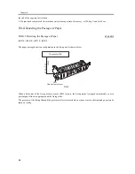
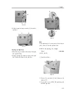
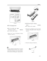
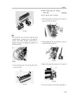
9.5.2.8
Removing the Pressure
Roller
0007-7918
iR2270 / iR2870 / iR3570 / iR4570
1) Remove the E-ring [1], and detach the drive gear
[2].
F-9-46
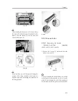
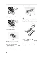
2) Lift the front of the pressure roller [1].
F-9-47
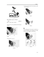
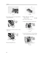
3) Push in the bush [1] found at the rear in the
direction of the arrow to free it; then, detach the
pressure roller.
F-9-48
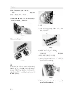
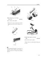
Be sure to pay attention to the position and the
orientation of the insulating bush.
F-9-49
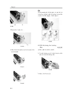
The insulating bush may be of 2 different shapes: one
for the iR3570/4570 and the other for the iR2270/
2870. If the machine is an iR2270/2870, be sure to pay
attention to the direction of the protrusion of the
insulating bush.
Содержание iR4570 Series
Страница 2: ...Download Free Service Manual And Resetter Printer at http printer1 blogspot com ...
Страница 6: ...Download Free Service Manual And Resetter Printer at http printer1 blogspot com ...
Страница 27: ...Chapter 1 Introduction Download Free Service Manual And Resetter Printer at http printer1 blogspot com ...
Страница 28: ...Download Free Service Manual And Resetter Printer at http printer1 blogspot com ...
Страница 81: ...Chapter 2 Installation ...
Страница 82: ......
Страница 84: ......
Страница 106: ...system setup network Ethernet driver setup auto detect ...
Страница 126: ...F 2 94 3 2 3 1 ...
Страница 127: ...Chapter 3 Basic Operation ...
Страница 128: ......
Страница 130: ......
Страница 136: ......
Страница 137: ...Chapter 4 Main Controller ...
Страница 138: ......
Страница 140: ......
Страница 164: ......
Страница 165: ...Chapter 5 Original Exposure System ...
Страница 166: ......
Страница 213: ...Chapter 6 Laser Exposure ...
Страница 214: ......
Страница 216: ......
Страница 221: ...P ACC Motor acceleration signal P DEC Motor deceleration signal BD BD output level single Single Description ...
Страница 230: ......
Страница 231: ...Chapter 7 Image Formation ...
Страница 232: ......
Страница 236: ......
Страница 249: ...F 7 13 1 2 3 4 ...
Страница 308: ......
Страница 309: ...Chapter 8 Pickup Feeding System ...
Страница 310: ......
Страница 316: ......
Страница 379: ...Chapter 8 8 63 An image is formed for the 1st side of the 5th sheet F 8 85 The 5th sheet is delivered 4 1 2 3 5 ...
Страница 464: ......
Страница 465: ...Chapter 9 Fixing System ...
Страница 466: ......
Страница 500: ...Chapter 9 9 32 F 9 107 3 Disconnect the connector 1 and detach the fixing film sensor 2 F 9 108 ...
Страница 501: ...Chapter 10 External and Controls ...
Страница 502: ......
Страница 506: ......
Страница 564: ......
Страница 565: ...Chapter 11 MEAP ...
Страница 566: ......
Страница 567: ...Contents Contents 11 1 Overview 11 1 11 2 MEAP Counter 11 2 11 3 Construction of the MEAP Platform 11 4 ...
Страница 568: ......
Страница 573: ...Chapter 12 Maintenance and Inspection ...
Страница 574: ......
Страница 576: ......
Страница 612: ......
Страница 613: ...Chapter 13 Standards and Adjustments ...
Страница 614: ......
Страница 616: ......
Страница 635: ...Chapter 14 Correcting Faulty Images ...
Страница 636: ......
Страница 675: ...T 14 22 Notation Description VR201 for factory use ...
Страница 676: ......
Страница 677: ...Chapter 15 Self Diagnosis ...
Страница 678: ......
Страница 680: ......
Страница 757: ...Chapter 16 Service Mode ...
Страница 758: ......
Страница 760: ...Contents 16 8 1 COPIER 16 102 16 8 1 1 Copier List 16 102 ...
Страница 869: ...Chapter 17 Service Tools ...
Страница 870: ......
Страница 871: ...Contents Contents 17 1 Special Tools 17 1 17 2 Oils and Solvents 17 2 ...
Страница 872: ......
Страница 875: ...Oct 8 2004 ...
Страница 876: ......


