


Chapter 9
9-24
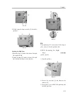
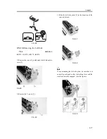
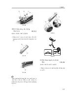
3) Slide the left side plate [1] in the direction of the
arrow to detach.
F-9-64
F-9-65
When mounting the left side plate, be sure that it is
correctly positioned so that the locking lever and the
teeth are correctly engaged. (See the figure.)
F-9-66
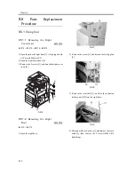
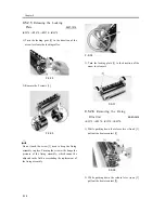
9.5.4.5
Releasing the Locking
Plate
0007-7902
iR2270 / iR2870 / iR3570 / iR4570
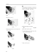
1) Turn the locking gear [1] in the direction of the
arrow to release the locking roller.
F-9-67
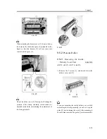
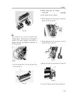
2) Remove the 2 screws [1].
F-9-68
Do not touch the screw [1] used to keep the fixing
assembly in place. Turning the screw will change the
pressure of the fixing assembly, which cannot be
adjusted in the field, necessitating the replacement of
the fixing assembly.
Содержание iR4570 Series
Страница 2: ...Download Free Service Manual And Resetter Printer at http printer1 blogspot com ...
Страница 6: ...Download Free Service Manual And Resetter Printer at http printer1 blogspot com ...
Страница 27: ...Chapter 1 Introduction Download Free Service Manual And Resetter Printer at http printer1 blogspot com ...
Страница 28: ...Download Free Service Manual And Resetter Printer at http printer1 blogspot com ...
Страница 81: ...Chapter 2 Installation ...
Страница 82: ......
Страница 84: ......
Страница 106: ...system setup network Ethernet driver setup auto detect ...
Страница 126: ...F 2 94 3 2 3 1 ...
Страница 127: ...Chapter 3 Basic Operation ...
Страница 128: ......
Страница 130: ......
Страница 136: ......
Страница 137: ...Chapter 4 Main Controller ...
Страница 138: ......
Страница 140: ......
Страница 164: ......
Страница 165: ...Chapter 5 Original Exposure System ...
Страница 166: ......
Страница 213: ...Chapter 6 Laser Exposure ...
Страница 214: ......
Страница 216: ......
Страница 221: ...P ACC Motor acceleration signal P DEC Motor deceleration signal BD BD output level single Single Description ...
Страница 230: ......
Страница 231: ...Chapter 7 Image Formation ...
Страница 232: ......
Страница 236: ......
Страница 249: ...F 7 13 1 2 3 4 ...
Страница 308: ......
Страница 309: ...Chapter 8 Pickup Feeding System ...
Страница 310: ......
Страница 316: ......
Страница 379: ...Chapter 8 8 63 An image is formed for the 1st side of the 5th sheet F 8 85 The 5th sheet is delivered 4 1 2 3 5 ...
Страница 464: ......
Страница 465: ...Chapter 9 Fixing System ...
Страница 466: ......
Страница 500: ...Chapter 9 9 32 F 9 107 3 Disconnect the connector 1 and detach the fixing film sensor 2 F 9 108 ...
Страница 501: ...Chapter 10 External and Controls ...
Страница 502: ......
Страница 506: ......
Страница 564: ......
Страница 565: ...Chapter 11 MEAP ...
Страница 566: ......
Страница 567: ...Contents Contents 11 1 Overview 11 1 11 2 MEAP Counter 11 2 11 3 Construction of the MEAP Platform 11 4 ...
Страница 568: ......
Страница 573: ...Chapter 12 Maintenance and Inspection ...
Страница 574: ......
Страница 576: ......
Страница 612: ......
Страница 613: ...Chapter 13 Standards and Adjustments ...
Страница 614: ......
Страница 616: ......
Страница 635: ...Chapter 14 Correcting Faulty Images ...
Страница 636: ......
Страница 675: ...T 14 22 Notation Description VR201 for factory use ...
Страница 676: ......
Страница 677: ...Chapter 15 Self Diagnosis ...
Страница 678: ......
Страница 680: ......
Страница 757: ...Chapter 16 Service Mode ...
Страница 758: ......
Страница 760: ...Contents 16 8 1 COPIER 16 102 16 8 1 1 Copier List 16 102 ...
Страница 869: ...Chapter 17 Service Tools ...
Страница 870: ......
Страница 871: ...Contents Contents 17 1 Special Tools 17 1 17 2 Oils and Solvents 17 2 ...
Страница 872: ......
Страница 875: ...Oct 8 2004 ...
Страница 876: ......


