


COPYRIGHT © 1998 CANON INC. CANON DADF-A1 REV.0 DEC. 1998 PRINTED IN JAPAN (IMPRIME AU JAPON)
2-43
CHAPTER 2 BASIC OPERATION
I. Controlling the Pick-Up Motor
1. Outline
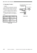
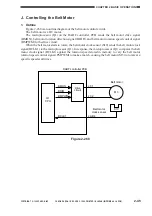
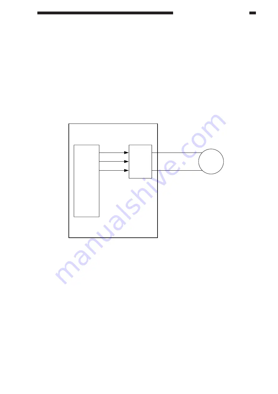
Figure 2-267 is a block diagram of the pick-up motor.
The feeder motor is a DC motor. The microprocessor (Q1) on the DADF controller PCB sends
to the drive circuit the pick-up motor drive signal (SMON), pick-up motor rotation direction signal
(SDIR), and pick-up motor rotation speed control signal (SMPWM).
In response, the drive circuit drives the pick-up motor according to these three signals.
The control circuit is not equipped with a circuit used to provide the microprocessor (Q1) with
feed back, indicating the state of pick-up rotation. As such, the pick-up motor rotation speed control
signal (SMPWM) remains constant at all times, and no correction is made when the rotation speed of
the pick-up motor fluctuates because of an external force.
Figure 2-267
Pick-up motor
DADF controller PCB
Drive
circuit
J12-1
M1
J12-2
Q1
CPU
SMON
SDIR
SMPWM


