


CHAPTER 5 TROUBLESHOOTING
5-14
COPYRIGHT © 1998 CANON INC. CANON DADF-A1 REV.0 DEC. 1998 PRINTED IN JAPAN (IMPRIME AU JAPON)
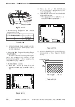
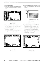
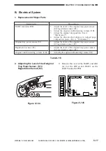
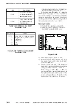
Glued in place
[1]
[2]
Glued in place
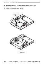
Figure 5-137
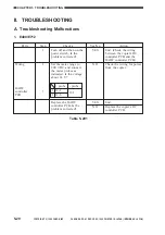
Feeding power (g)
520±20
570±20
Test strip
64 g/m
2
80 g/m
2
Table 5-109 Feeding Power
Note:
As a guide, try to limit the difference in
feeding power between front and rear.
Table 5-110
Adjusting Screw and Feeding Power
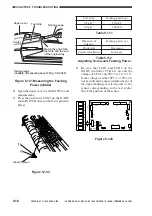
9) Likewise, adjust the feeding power at the
rear.
10) Measure the feeding power at front and
rear once again. If the measurements are as
indicated, firmly tighten the lock nut and
glue it in place. Otherwise, make
adjustments once again.
Feeding power
Decreases
Increases
Direction of
rotation
Clockwise
Counterclockwise
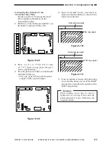
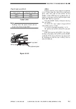
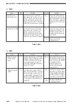
Points to Note When Taking
Measurements
1. Be sure that the three separation belts
are in contact with the test strip.
2. Be sure that the test strip is pulled
straight along the separation belt (Figure
5-131).
3. Be sure that measurements are taken
when the rear end of the test strip and the
rear end of the original tray are flush
(Figure 5-136).
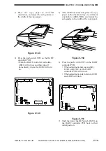
Figure 5-136
Measuring the Feeding Power (front)
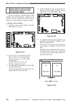
7) Open the upper cover of the DADF to end
measurement.
8) Loosen the lock nut 1 used to keep the
front, and turn the adjusting screw 2 until
the feeding power is as indicated. Then,
tighten the lock nut 1.
Upper cover
Test strip
Spring
(rear)
(front)
Match the end of the
test strip and the end
of the original tray.
Spring gauge:capable of measuring about 600g
(Tool No.CK-0058)


