


COPYRIGHT © 1998 CANON INC. CANON DADF-A1 REV.0 DEC. 1998 PRINTED IN JAPAN (IMPRIME AU JAPON)
2-5
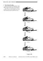
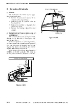
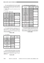
CHAPTER 2 BASIC OPERATION
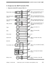
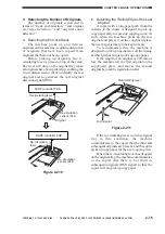
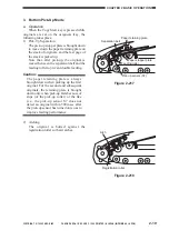
D. Outputs to the DADF Controller PCB
1. Outputs to the DADF Controller PCB (1/1)
Stopper plate solenoid
When '0', the solenoid (SL1) turns on.
(The stopper plate moves down.)
SL1
J217
1
2
J5-10
-11
+24V
STPSL
2
1
Paper retaining plate
solenoid
When '0', the solenoid (SL2) turns on.
(The paper retaining plate moves down.)
SL2
J216
1
2
J5-12
-13
+24V
WGTSL
2
1
Stamp solenoid
When '0', the solenoid (SL4) turns on.
(The stamp puts a marking on the
original.)
SL4
J220
1
2
J14-9
-10
+24V
SMPSL
Clutch
When '0', the clutch (CL1)
turns on.
CL
J13-1
-2
+24V
CL
Brake
When '0', the brake (BK1)
turns on.
BK
J6-1
-2
+24V
BK
Pick-up motor
See p. 2-43.
M1
J12-1
-2
Feeder motor
When '0', the feeder motor (M2)
turns on.
M2
J11-1
-2
+24V
FMPWM
Belt motor
Delivery motor
See p. 2-45.
M3
J7-1
-2
When '0', the delivery motor (M5)
turns on.
M5
J14-8
-7
+24V
EMPWM
Re-circulation motor
Display PCB
LED101
LED102
When '0', the re-circulation motor (M4)
turns on.
M4
J8-5
-6
-3
-4
J102-1
-2
J101 -5
-6
-3
+5V
RSDRV
When '0', the Original Set indicator
turns on.
+5V
ORGLED
2
1
1
2
3
2
J221
J101-4
Paper deflecting plate
solenoid
When '0', the solenoid (SL3) turns on.
(The paper deflecting plate operates.)
SL3
J9-B2
-B1
+24V
FLPSL1


