background image

CHAPTER 5.  TROUBLESHOOTING

5–15

5

. Changing the parallel interface

communication mode

With some types of computers which com-

municate in the compatible mode, the timing of

the Busy and Ack signals may need to be

changed as the communication may not be

done correctly.

In most computers, communication can be

carried out normally using the "A-B (Default)"

setting.  However, if the data reception indica-

tor on the printer does not light up when data is

transferred, the communication mode should be

switched by following the procedure below.

1)  Turn OFF the power switch.

2)  While pressing both the ONLINE and

ENTER keys, turn ON the power switch

to display the "Parallel Interface Commu-

nication select Mode."

•  Confirm that "Busy-Ack" is displayed on

the message display and release the keys.

Busy-Ack

   A-B (Default)

3)  Press the left or right arrow key to display

the desired communication mode.

4)  Press the ENTER key to confirm the

displayed mode.

•  When a "*" mark is displayed after the

name of communication mode, execute

the initial operation and return to the

normal menu.

Busy-Ack

   A-B (Default)*

Initializing

REFERENCE:

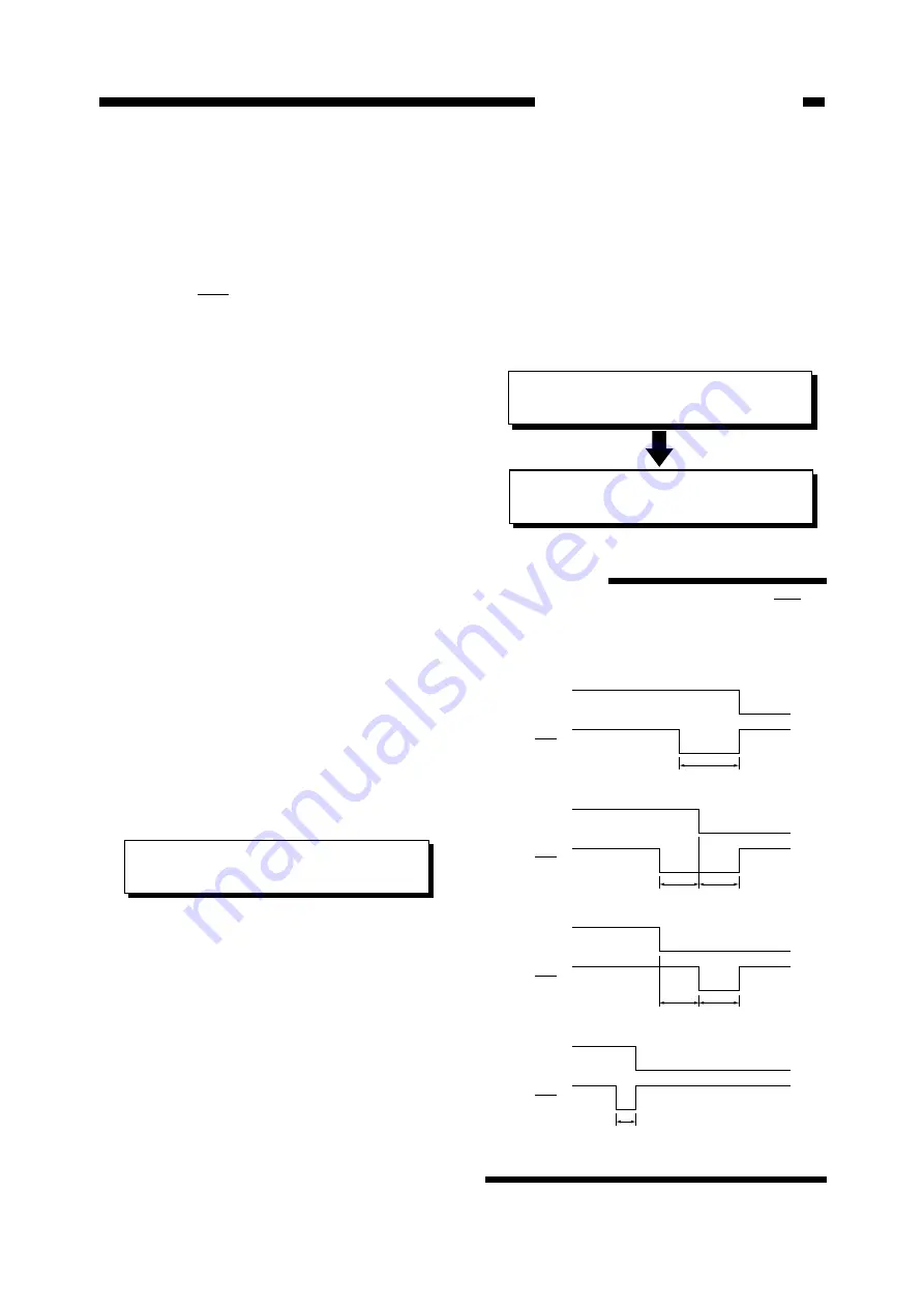
Relationship between the Busy and Ack

signals in each communication mode :

Figure 5-203

Busy

Ack

• A - B (Default) [Ack-in-Busy]

4080ns

Busy

Ack

• A - B - A [Ack-while-Busy]

3264ns

3264ns

Busy

Ack

• B - A [Ack-after-Busy]

3264ns

3264ns

Busy

Ack

• A - B (Fast) [Ack-in-Busy(fast)]

1200ns

Содержание BJ-W3000

Страница 1: ...QY8 1366 000 REVISION 0 COPYRIGHT 2000 CANON INC CANON BJ W3000 3050 0100 GR 0 40 0 PRINTED IN JAPAN IMPRIME AU JAPON JAN 2000 ...

Страница 2: ...0000 GR 0 40 0 ...

Страница 3: ......

Страница 4: ...countries where such provisions are inconsistent with local law Trademarks The product names and company names appearing in this manual are the registered trademarks or trademarks of the individual companies Copyright This manual is copyrighted and all rights reserved Under the copyright laws this manual may not be copied reproduced or translated into other languages in whole or in part without th...

Страница 5: ...eration Operation of mechanical and electric functions Chapter 3 Mechanical System Mechanical setup and assembling disassembling procedure Chapter 4 Maintenance and Servicing Periodic parts replacement Standard service life of consumables Periodical services points of maintenance and inspections Chapter 5 Troubleshooting Service mode adjusting and settings operation trouble correction image troubl...

Страница 6: ...imited to block diagrams 4 Troubleshooting is described using procedural tables The procedural table is a variation of a general flow chart An example is shown below e g No power is supplied 1 2 3 NO NO YES Connect the power code to the machine and outlet Explain to the customer that the trouble is not attributable to the machine Remove the cause of the blown fuse and replace the DC power PCB Is t...

Страница 7: ...ddress of the circuit diagram is shown by applicable pages of each controller indicated at the upper right of the circuit diagram and its location CAUTION Connect in the power code to the machine and outlet Is the power cord properly connected to the receptacle on the machine and outlet YES NO 1 Remedy Check item Result Step Explain to the customer that the trouble is not attributable to the machi...

Страница 8: ... 1 39 D After Printing 1 39 VII USER MAINTENANCE 1 40 A Head Cleaning 1 40 B Normal Cleaning 1 40 VIII INSTALLATION ENVIRONMENT 1 41 IX PACKAGE CONFIGURATION 1 42 X TRANSPORTING THE PRINTER 1 43 I BASIC OPERATION 2 1 A Functional Configuration 2 1 B Interface Input Output 2 2 1 Parallel interface 2 2 2 Serial interface 2 6 C Image Controller 2 7 D Engine Controller 2 10 E Engine controller Input O...

Страница 9: ...in Parts 3 2 2 Outline of disassembly and assembly of main parts 3 3 PRECAUTIONS FOR DISASSEMBLY AND REASSEMBLY 3 5 I EXTERNALS 3 7 A External Cover 3 7 1 Removing the right cover 3 7 2 Removing the upper cover and front cover 3 7 3 Removing the lower cover 3 8 4 Removing the front cover switch 3 9 B Operation Panel 3 9 1 Removing the operation panel 3 9 C Fan 3 10 1 Removing the cooling fan 3 10 ...

Страница 10: ...2 3 004xx BJ Print head system 5 23 4 005xx Ink tank system 5 24 5 007xx Purge system 5 24 6 008xx Cutter system 5 25 7 011xx Engine controller 5 25 8 012xx Internal communication system 5 26 9 015xx Power supply related 5 26 10 021xx User adjusted system 5 26 11 051xx Image controller 5 27 12 052xx Serial interface communication system 5 27 13 053xx Parallel interface communication system 5 27 14...

Страница 11: ...oes not working 5 41 28 Media is not fed 5 42 29 Suction fan does not rotate 5 42 V CORRECTION OF IMAGE DEFECTS 5 43 A Initial Inspection 5 43 1 Installation environment 5 43 2 Media check 5 43 B Corrective Procedures for Image Defects 5 44 1 Non ejection of ink 5 44 2 Vertical misalignment 1 5 45 3 Vertical misalignment 2 5 46 4 Low resolution 5 47 5 Dislocation of dots of different colors 5 47 6...

Страница 12: ...ix PREFACE ...

Страница 13: ... Paper Thickness Adjustment Lever 1 31 IV CARTRIDGE REPLACEMENT 1 32 A Replacing the BJ Print head 1 32 B Replacing the Ink Tank 1 34 V SIMM REPLACEMENT 1 36 A About SIMM 1 36 B SIMM Installation 1 36 C SIMM Removal 1 37 VI CAUTIONS ON HANDLING 1 38 A Cartridges 1 38 B Paper Storage Environment 1 39 C Paper 1 39 D After Printing 1 39 VII USER MAINTENANCE 1 40 A Head Cleaning 1 40 B Normal Cleaning...

Страница 14: ...edia delivery system Face up delivery in front Max delivery sheets 5 sheets Plain paper Fixing method Natural drying Cutter Automatic cutter replaceable 2 Exterior A0 size model External dimensions main unit only 1462 x 388 x 345 mm External dimensions including stand 1462 x 700 x 1204 mm Weight Main unit only Approx 31 kg Weight including stand Approx 46 kg A1 size model External dimensions main ...

Страница 15: ...d 2 pass Uni 360dpi x 360dpi 7 2kHz Bk L Color S 9 Color high enhanced 4 pass Unil 360dpi x 360dpi 7 2kHz Bk L Color S 1 Bi bi directional Uni uni directional 2 Equivalent 3 S small dot M middle dot L large dot Table 1 101 Media type Monochrome Color Draft Normal Enhanced High resolution Draft Normal Enhanced Maximum printing speed Plain paper mode Print mode A0 size A1 size Monochrome mode Color ...

Страница 16: ... pass uni directional at 20 duty 5 for each color Interface Parallel interface Complies with IEEE1284 Compatible mode Nibble mode Connector complying with IEEE1284 B Receptacle Serial interface Complies with RS 232C DCE D Sub 9 pin female connector Emulation Complies with HP GL HP GL 2 and HP RTL Kanji font Kanji JIS first and second standard Memory Standard 8MB can be increased to 72 MB 72 pin 60...

Страница 17: ...a types Plain paper coated paper tracing paper and matte film 75 100µm Paper thickness 75 165µm excluding matte film 64 128g m 2 Maximum paper width A0 model 914mm A1 model 634mm Minimum paper width length Width 250mm Length 150mm Maximum printing length Cut sheet media 1250mm Roll media Windows95 98 driver 4 6m WindowsNT4 0 driver 4 6m ADI driver 13m HDI driver 18m Printing length of roll media v...

Страница 18: ... 44 0 NG NG OK NG D 558 8 863 6 22 0 34 0 OK NG OK OK C 431 8 558 8 17 0 22 0 OK OK OK OK B 279 4 431 8 11 0 17 0 OK OK OK OK A 215 9 279 4 8 5 11 0 NG OK NG OK ANSI ARCH 6 914 4 1219 2 36 0 48 0 NG NG OK NG 5 762 0 1066 8 30 0 42 0 NG NG OK NG 4 609 6 914 4 24 0 36 0 OK NG OK OK 3 457 2 609 6 18 0 24 0 OK OK OK OK 2 304 8 457 2 12 0 18 0 OK OK OK OK 1 228 6 304 8 9 0 12 0 NG OK NG OK ISO Over A0 ...

Страница 19: ...el Complies with ISO 9296 When operating Approx 52dB A or less At stand by Approx 20dB A or less Operating environment Temperature 5 35 C Printing quality assured 15 30 C Humidity 10 90 RH Printing quality assured 20 80 RH Atmospheric pressure 1013 709hPa Storage environment Temperature 0 35 C Humidity 5 95 RH Should be free from condensation and rapid temperature variations ...

Страница 20: ...NERAL DESCRIPTION 1 7 II NAMES OF COMPONENTS A External View Figure 1 201 1 8 7 6 5 4 2 3 1 Front cover 2 Carriage 3 Operation panel 4 Paper release lever 5 Wiper Cleaner blade 6 Cutter unit 7 Platen 8 Pinch roller ...

Страница 21: ...elease hook 3 Paper thickness adjustment lever 4 BJ Cartridge 5 Ink tank release hook 6 Cutter unit Figure 1 202 C Cable Connections 1 Parallel interface connector 2 Serial interface connector 3 AC inlet 4 Earth wire terminal 5 Power switch Figure 1 203 1 2 3 4 5 6 1 2 3 4 5 ...

Страница 22: ...kward direction Paper feed forward direction Carriage forward direction Carriage backward direction Figure 1 204 E Printing Direction 6 5 4 3 2 1 4 Parallel interface connector 5 AC inlet 6 Power switch 1 Roll media stopper 2 Spindle 3 Serial interface connector Figure 1 205 ...

Страница 23: ...d Divided into upper and lower sections 3 Power lamp Green when power switch is turned on Orange in the sleep state Blinks orange if an error occurs 4 Online key Switches between the online offline and menu states 5 Enter key Enters selected menu item 6 Right left arrow keys Used when selecting parameters Also used to move the carriage on the platen 7 Up down arrow keys Used when selecting menus C...

Страница 24: ... states when the Online key is pressed 1 Some menus cannot be setup during printing 2 When no media is loaded the machine cannot be returned to the Online state by pressing the Online key It returns to Offline 3 Pressing any key on the control panel opening the front cover or receiving data in Sleep state will wake the printer up Media setup Menu setup screen Printing Data received After printing ...

Страница 25: ... as there is sufficient space in the buffer memory data is received and analyzed continuously When the reception buffer becomes almost full in the pause state the mode is shifted to receive data at 1 byte sec By pressing the online key in the pause state the printer will enter the menu state Menus and parameters can be set up The menu items available when paused are more limited than those availab...

Страница 26: ...ute 2 minutes 5 minutes 10 minutes 30 minutes 60 minutes Interface Setup English mm English inch Francais Deutsch Italiano Espanol Svenska Hardware Xon Xoff On Off Yes No Print Length Band Joint Demonstration Menu Map Color Palette Setup List Nozzle Check Dump Mode I C Ver I Boot Ver E C Ver E Boot Ver E Slv Ver Memory Error I C Ver I Boot Ver E C Ver E Boot Ver E Slv Ver Memory Error Printing Men...

Страница 27: ...us and parameters are selected as described below 1 By pressing the online key in the offline or pause state the printer enters the menu state 2 Select a menu item by pressing the right and left arrow keys 3 After selecting a menu move to the parameter menu by pressing the down arrow key CAUTION Menu display varies depending on the state offline or pause 4 Select parameters by pressing the right a...

Страница 28: ...y adjusted Auto Band Adj Paper feed rate is automatically adjusted 5 Print Mode a Print Quality Default Normal The print quality can be selected for the type of data or paper Draft For higher speed lower quality output Normal For printing line drawings etc Enhanced For printing files including graphics or solid printing High Resolution monochrome only For printing monochrome line draw ings at an e...

Страница 29: ...n of 5mm Large Leaves a margin of 15mm d Copies Default 1 Specify the number of copies to be printed 1 99 7 Auto Cut a Cut Type Default Cut Select the type of cut for roll media after completion of printing Cut Cuts the roll media automatically after completion of printing Cut Line After completion of printing a cutting line is printed No Cut After completion of printing the roll media is not cut ...

Страница 30: ... is used See Table 1 305 Pen Table 1 to 3 Pen setup pen table stored in the printer can be used See Table 1 304 CAUTION In the draft mode the ink may not dry depending on the environment Set the drying time as required REFERENCE Drying time for each media type is as follows Plain paper 30 sec Coated paper none Tracing paper 2 min Film 7 sec 8 Emulation Default Auto Sense Emulation can be set to ma...

Страница 31: ...d to the defaults All Pen Table All pen table values are reset to the default values Pen Table 1 3 Values of the selected pen table are reset to the default values 10 Line Type a Line Intersect Default Overlay Color processing method for overlapping lines or figures can be set Overlay Overlapping parts are printed in the color applied last Merge Overlapping parts are printed using mixed colors b L...

Страница 32: ...1 Color Joint 0 3 0 6 1 1 1 6 2 2 2 6 3 3 3 6 4 4 4 6 5 5 5 6 6 7 6 6 7 9 7 6 8 11 8 6 9 13 9 6 10 15 10 6 11 17 11 6 12 19 12 6 13 21 13 6 14 23 14 6 15 25 15 6 Table 1 304 1 When the display language is other than katakana the widths are all set to 3 Software pen table factory settings Figure 1 303 Pen No Width Color Joint 2 0 3 0 6 1 3 1 6 2 3 2 6 3 3 3 6 4 3 4 6 5 3 5 6 6 3 6 6 7 3 7 6 2 When ...

Страница 33: ...s data the data is printed on the margin If the later data does not fit into the width of the margin of the previous data the data is not printed on the margin but printed to the next printing position Media Save Automatic paper saving layout Con tinuous data is rotated clockwise so that paper feeding rate is minimized The image data is printed to the left end of the paper Best Automatic layout fo...

Страница 34: ...CHAPTER 1 GENERAL DESCRIPTION 1 21 A A A A A 5mm A A A A 5mm A A A A 5mm Nesting Media Save Best Figure 1 304 ...

Страница 35: ...rally On File is reversed laterally e Layout Size roll media only Default ISO A Paper size can be set ISO A ISO B JIS B ANSI ANSI ARCH ISO Over EURO DIN KOREAN Custom f User Size roll media only Width and length of paper to be printed can be set Default A0 model 84 1 x 118 9 cm A1 model 59 4 x 84 1 cm Width Width can be set from 8 0 to 62 7 91 4 cm in one mm units Length Length can be set from 8 0...

Страница 36: ...sfer to start of printing will be as specified here 10 sec 30 sec 1 min 2 min 5 min 10 min 30 min 60 min 13 System Setup Configuration of the system setting menu as follows a Language Default previos setting preserved Language to be indicated on the message display can be selected English mm Display in English mm Factory setting English inch Display in English inch katakana Display in Japanese Fra...

Страница 37: ...eset to the default values No User menu settings are not reset e Information Default On Image controller PCB and engine control ler PCB versions and memory capacity are displayed 14 Self test Print A self test pattern can be printed to check the printer operation Demonstration A built in demonstration pattern is printed Menu Map A list of menus is printed Color Pallet A color pallet of 0 to 255 is...

Страница 38: ...able to the printer or the computer The current menu settings service mode values and a history of the last 4 errors which occurred are printed in the setup list and can be filed for reference or faxed to the service depart ment Figure 1 305 shows a sample of a setup list and Table 1 306 explains the information in the setup list Figure 1 305 4 5 6 9 7 8 10 1 2 3 11 ...

Страница 39: ... auto cutting setting Drying time setting Auto layout setting Zoom setting Rotation setting Y mirror setting Layout size setting User defined size setting Length setting Width setting Nesting timer setting Line intersecton setting Line shading setting Baud rate setting Data bit parity setting Hand shake setting EOP timer setting Emulation setting Auto adjust mode setting Paper feeding priority set...

Страница 40: ...ump output is com pleted Therefore to execute a dump again reselect Dump mode and then transfer the file data CAUTION If data is transferred continuously the final portion cannot be correctly dumped To prevent trouble transfer only one file at a time in the dump mode 6 Image layout a Data size recognition standard This machine recognizes the size of data received as follows 1 PS Plot size recognit...

Страница 41: ...tic rotation Automatic rotation Automatic rotation Follow the set value Automatic rotation Automatic rotation Automatic rotation Follow the set value Horizontal arrangement Done Not done Not done Not done Done Not done Not done Not done Y mirror scale Done Done Done Done Done Done Done Done Panel rotation Not done Not done Not done Done Not done Not done Not done Done Nesting Best Media save Off N...

Страница 42: ...over 4 Load paper into the printer a In the case of cut sheets 1 Lower the paper release lever 2 With the printed surface of the paper upward match the paper edge to the inside of the paper matching line and raise the paper release lever When the paper inserted below the pinch roller unit is detected by the PE sensor the suction fan runs and the paper is sucked to the platen If the printer does no...

Страница 43: ...paper The printer detects the paper size and feeds the paper to the printing start position After completion of loading the printer enters the online state REFERENCE If the paper loads crooked or jams press any key on the operation panel to stop the loading process 7 File data is transferred from the computer in the online state and printing is started To stop printing press the online key to ente...

Страница 44: ...e the paper thickness adjustment lever to adjust the head to platen distance Standard position Set to this position when printing high density graphics graphic position Set to this position if the paper still rubs the head after being set to the graphic position Figure 1 309 4 Close the front cover The carriage returns to the home position CAUTION Better print quality can be obtained by narrowing ...

Страница 45: ... referring to Chapter 5 V CORREC TION OF IMAGE DEFECT If ink is still not discharged replace the BJ print head A Replacing the BJ Print head CAUTION When handling the BJ print head take care not to touch the head on elec trodes Replace the BJ print head only at the cartridge replacement position Electrode Head Figure 1 401 1 Press the right and left keys in the offline or pause state to move the c...

Страница 46: ... touch the BJ print head and carriage electrodes Do not reuse the protective cap and protective seal Take care not to bump the head against the platen or carriage 7 With the head facing down insert the BJ print head into the carriage Figure 1 404 Figure 1 405 Figure 1 406 10 Install the real ink tank 11 Close the front cover The carriage returns to the home position and head cleaning is carried ou...

Страница 47: ... and re move it Figure 1 410 B Replacing the Ink Tank CAUTION Replace the ink tank only at the cartridge replacement position 1 Press the right and left keys in the offline or pause state to move the carriage to the cartridge replacement position 2 Open the front cover 3 Press the ink tank release hook and re move the ink tank Figure 1 409 CAUTION Do not touch the ink tank outlet Outlet Figure 1 4...

Страница 48: ...R 1 GENERAL DESCRIPTION 1 35 6 Install the ink tank Figure 1 411 CAUTION Push the ink tank in until it clicks 7 Close the front cover The carriage returns to the home position and head cleaning is carried out ...

Страница 49: ...4 8 16 or 32 MB No of pins 72 Access speed 60ns or faster FPM high speed page mode compatible No parity EDO memory can be also used but it is operated as FPM memory Two SIMMs can be added so that the memory capacity can be increased by up to 72MB with the standard memory Figure 1 501 2 Holding both ends of the SIMM with it centered in the expansion slot insert it from the right CAUTION When handli...

Страница 50: ...move the 4 screws 1 and the cover plate 2 Figure 1 504 2 Gently pull back the two hooks 3 at each end of the SIMM Roll the SIMM to the right and remove it 2 1 Figure 1 505 3 Attach the cover plate 2 and tighten the 4 screws 1 3 Figure 1 503 4 Attach the cover plate 2 and tighten the 4 screws 1 REFERENCE When only one SIMM is used it must be installed in the left slot SIM601 When adding two SIMMs i...

Страница 51: ... shake the BJ print head after removing the protective seal Do not remove the BJ print head from thie printer except when replacing it or disassembling the main unit Only unpack a new BJ print head imme diately before replacing an old one Do not disassemble or modify the BJ print head Figure 1 601 2 Cautions on handling ink tanks Do not touch the outlet Do not remove the ink tank from the BJ print...

Страница 52: ...r that is not curled folded or wrinkled For handling the paper be careful not to curl it or damage the printing side hold the paper only at the ends outside of the printed area to prevent oil or moisture transferring from your hands to the paper or wear cotton gloves Take out each sheet from the wrapping paper immediately before using it D After Printing Since the ink may still be wet do not touch...

Страница 53: ...nd increases a nozzle may become plugged resulting in white streaks on the image In such a case the user should execute the Head cleaning in the main menu to clean the head CAUTION Repeated head cleaning will consume excessive ink Explain to the user that head cleaning should only be performed when defective images occur B Normal Cleaning Instruct the user to clean the following places every month...

Страница 54: ... and refrigerators Locations where there might be alcohol thinner etc nearby Places where temperature or humidity fluctuates often Air from an air conditioning system or electric fan directly blowing on the machine Be cautious about the following when installing the machine Adjust the media so as not to touch the floor to prevent it from picking up dust or dirt Explain to the client that the floor...

Страница 55: ...ACKAGE CON FIGURATION The package configuration of the printer when shipped from the factory is shown in the figure below 1 3 2 4 Figure 1 901 1 Printer 2 Spindle Roll media stopper 3 BJ print heads black cyan magenta yellow 4 Accessory box ...

Страница 56: ...nd by hand 3 Fold a sheet of A1 size paper or A0 size paper twice and insert it between the pinch rollers 4 Fix the carriage belt at the center of the platen by holding it with a clip as shown in Figure 1 1001 so as not to allow the carriage to move Figure 1 1001 CAUTION Take care not to damage the carriage belt and linear scale 5 Remove the roll media and spindle 6 Fix the front cover closed with...

Страница 57: ...Encoder 2 26 D Media Sensor 2 28 E Detection of the Ink Tank 2 34 F Remaining Ink Detection 2 35 G Cutter Unit 2 38 III BJ CARTRIDGE 2 39 A BJ Cartridge 2 39 B BJ Print head Drive 2 43 IV PURGE UNIT 2 46 A Outline 2 46 B Capping Function 2 51 C Head Cleaning 2 52 D Waste Ink Absorber Unit 2 56 V FEEDER UNIT 2 57 A Outline 2 57 B Paper Feed Motor Control 2 58 C Feeding Operation 2 60 VI FAN 2 63 VI...

Страница 58: ...mposed of 5 blocks image processing control system carriage BJ cartridge unit purge unit and feeder unit Figure 2 101 Carriage Purge unit Feeder unit Image processing control system Engine controller Image controller External interface BJ cartridge unit 2 1 CHAPTER 2 BASIC OPERATION ...

Страница 59: ...direction No Compatible Nibble PC to the printer No Compatible Nibble PC to the printer 1 Strobe HostClk 19 GND 2 Data 1 20 GND 3 Data 2 21 GND 4 Data 3 22 GND 5 Data 4 23 GND 6 Data 5 24 GND 7 Data 6 25 GND 8 Data 7 26 GND 9 Data 8 27 GND 10 Ack PtrClk 28 GND 11 Busy PtrBusy 29 GND 12 Perror AckDataReq 30 GND 13 Select Xflag 31 Init 14 AutoFd HostBusy 32 Fault DataAvail 15 Not used 33 GND 16 GND ...

Страница 60: ... Ack while Busy 3264ns 3264ns DATA1 8 BUSY STROBE ACKNLG B A Ack after Busy 3264ns 3264ns DATA1 8 BUSY STROBE ACKNLG A B Fast Ack in Busy fast 1200ns b Compatible mode The compatible mode is applicable to cases as shown below The compatible mode can be switched by changing the BUSY and ACKNLG timing in the Centro timing setting mode ...

Страница 61: ...gnal and responds by setting the BUSY signal to H When data processing has been completed the printer outputs the ACKNLG signal to notify the computer that the data has been accepted When data reception is possible it sets the BUSY signal to L The Perror signal becomes H to indicate a warning or error in the printer The Select signal becomes H to indicate that the printer is in a printing mode onl...

Страница 62: ... changes the HostBusy signal to H indicating that the data has been received The printer issues the PtrClk signal and the first handshaking is completed The printer confirms the second fall of the HostBusy signal and outputs the high order 4 bits to the control signal lines The computer accepts the data in the same way as before When the HostBusy signal goes active and there is no more data to be ...

Страница 63: ...signal from the printer the computer starts transmission of data TD to the printer The printer stores the data from the computer in its buffer and processes the data in succes sion However if the printer processing speed is slower than the computer s the buffer soon becomes full so that no more data can be stored When the empty space in the buffer decreases below a specified value the printer turn...

Страница 64: ... 4 SRAM U628 3 DRAM U602 606 U611 U616 2 FIFO U622 1 Serial controller U632 7 Gate array U617 10 EEPROM U619 Operation Panel 11 PIO U629 U634 8 bit Data bus Address bus 32 bit Data bus Address bus 13 Reset IC U613 Image controller External serial interface 16 bit data bus 32 bit data bus 8 bit 8 bit data bus Y601 14 7MHz External parallel interface 6 Serial controller U633 Communication I F 5 Time...

Страница 65: ...U system processing work area 4 SRAM U628 32 Kbyte memory used to store the raster slice converted image data until a trans mission request is received from the engine controller 5 Timer U610 Uses the by external clock of 14 7MHz divided by 2 Functions as a baud rate clock for the serial controllers U632 U633 6 Serialcontroller U633 Uses the external clock of 14 7MHz divided by 2 Intermediary betw...

Страница 66: ... on the printer and the values set using the operation panel 11 PIO U634 Intermediary between the CPU U607 and operation panel input output port 12 CPU U607 Uses the external 33 MHz clock Major functions are as follows Controls the image controller Vector raster conversion Raster raster conversion Controls communication with the engine controller 13 Reset IC U613 Resets the CPU U607 at power ON 14...

Страница 67: ...ata I F 8 bit Image data control communication I F Engine controller 2 Sub CPU U202 Purge motor BJ cartridges Bk C M Y LED Carriage controller 1 CPU U221 3 DRAM U216 4 FLASH ROM U219 8 Gate array U212 9 Gate array U204 Y202 16MHz Command communic ation I F 6 Reset IC U227 Image controller Carriage motor 11 Carriage motor driver U232 Paper feed motor 10 Paper feed motor driver U233 7 Gate array U20...

Страница 68: ...232 Generates carriage motor drive signal 12 Purgemotordriver U234 Generates purge motor drive signal Major functions of the ICs on the engine controller are as follows 1 CPU U221 Connected to the DRAM U216 FLASH ROM U219 EEPROM U218 and gate array U204 U212 via the address bus and data bus Run by the 16MHz external clock Major functions are as follows Command communication with the image controll...

Страница 69: ...V When 0 PS3 turns on When there is no ink in the ink chamber 0 INKCONN INK1_IN J213 5 6 8 7 1 2 4 3 J11 4 3 1 2 5V 5 4 3 1 2 3 5 4 3 Pump position sensor When the guide roller is at home position 1 PURHP_IN 5V 1 2 3 8 7 6 When the carriage is at home position 1 CRGHP_IN PS2 Home position sensor PS1 4 5 6 8 7 6 1 2 3 Remaining ink sensor 5V 1 2 3 J214 3 2 1 When PS6 has detected paper 0 MEDIA_IN P...

Страница 70: ...tes During rotation 1 FAN_CONT Suction fan Cooling fan Engine controller 1 2 J5 1 2 Purge motor M3 1 2 3 4 5 6 J9 J202 1 2 3 4 5 6 1 2 3 4 5 6 PG_OUT1 PG_OUT2 PG_OUT3 PG_OUT4 PPOW_CONL PPOW_CONL J204 1 2 26V FM2 FANSTS J206 2 3 1 Paper feed motor M1 1 2 3 4 5 6 J12 J203 1 2 3 4 5 6 1 2 3 4 5 6 Carriage motor J201 1 2 3 4 5 6 YA YAN YB YBN XA XAN XB XBN 26V 26V M2 FAN_CONT Rotation control signal W...

Страница 71: ...M J505 BJ cartridge Y J506 C M Y J208 J207 J501 J502 Media sensor J207 J502 PS9 J502 33 32 5V Linear sensor Rectanguler wave with phase difference of 90 input at the time of carriage movement J509 3 4 2 1 J207 8 9 PS8 Bk See Media sensor page 2 28 3 1 4 5 TH1 THERM_IN Internal temperature signal from thermistor 2 1 LSA LSB J510 6 4 8 7 5 3 5V 26V LEDB LEDR REGOUT POUT 4 37 ...

Страница 72: ... print head Head rank measurement Front cover open close detection Software initial check CPU initialization ROM RAM check EEPROM check Error indication E011xx E012xx E051xx Normal Yes No Closed Yes No Error indication E004xx W004xx Normal If there is no BJ print head color C M Y warning and black Bk error are indicated Yes No Close the front cover Power switch SW1 ON A ...

Страница 73: ...e power switch is turned ON Online Offline Error indication E003xx E005xx E007xx Normal Yes No Error indication E001xx E003xx E008xx E015xx Normal Yes No Present Yes No A Initial operation Linear encoder check Home position detection Pump position detection Ink tank presence detection Remaining ink detection BJ print head reference position detection Error indication E003xx E005xx E007xx Normal Ye...

Страница 74: ...ling fan FM2 Rotation Always detect while the fan is rotating Rotates for 60 sec after detection of media Error indication E01501 Normal Yes No Closed Yes No Close the front cover Message indication Present Yes No Set media Press the up or down arrow key Load the media See page 2 30 for details Online Error indication E001xx E003xx E008xx E015xx Normal Yes No ...

Страница 75: ...cation Front cover open close detection Check communication condition Closed Yes No Close the front cover Message indication Present Yes No Set media Load the media See page 2 30 for details Error indication E001xx E003xx E008xx E015xx Normal Yes No Error indication E052xx E053xx Normal Yes No A ...

Страница 76: ...x W067xx Normal Yes No A Suction fan FM1 Cooling fan FM2 Rotation Always detected when rotating Error indication E01501 Normal Yes No B Purge action See page 2 48 49 50 for details Checking the time having been left Error indication E005xx Normal Yes No Less than 72 hours from the previous purging Yes No ...

Страница 77: ...d position Move the carriage to the home position Suction fan FM1 and cooling fan FM2 stopped Cutting operation See page 2 38 for details B Cut sheet media Yes No Offline Online Check print head Always detected while printing Printing started End of printing Error indication E004xx W004xx Normal Yes No ...

Страница 78: ...CHAPTER 2 BASIC OPERATION 2 21 ...

Страница 79: ...arriage through the carriage belt causing the carriage to move back and forth over the paper The distance it moves is controlled by counting the number of pulses of the signal transmitted from the engine control ler to the carriage motor The print signal from the engine controller is transmitted to the BJ print head mounted to the carriage via the carriage controller Figure 2 201 1 2 3 4 5 6 7 8 9...

Страница 80: ...and move back and forth by the driving force from the carriage motor M2 Selects one of 3 distances between the head and platen Rises and lowers according to the movement of the carriage cutting the roll media Detects ink dot position when adjusting the print position alignment Also detects internal temperature with a built in thermistor Transmits the driving force of the carriage motor M2 to the c...

Страница 81: ...motor supply current control 2 Operation a ON OFF control Carriage motor ON OFF is controlled by the carriage motor driver control signal MTP12 15 issued by the CPU to the carriage motor driver on the engine controller When MTP12 15 are 0 the carriage motor driver generates motor drive pulses YMA YMAN YMB YMBN and the carriage motor M2 is rotated by those pulses On the other hand when MTP12 15 are...

Страница 82: ...urrent supplied to the carriage motor M2 by the carriage motor driver for stopping holding low speed operation and high speed operation By changing the carriage motor supply current according to the current condition of the carriage motor M2 the carriage motor M2 is smoothly controlled e Detection of problems If a heavy load is placed on the carriage for any reason the pulse signal output from the...

Страница 83: ...oming through the slit pattern and outputs 4 signals A A B B to the signal processing circuit Two comparators output rectangular waves LSA LSB with a phase difference of 90 C Linear Encoder 1 Outline A linear encoder is installed on the printer to allow checking the carriage operation and ad justing the dot placement position on the paper When the carriage is returning after the home position sens...

Страница 84: ... LSA signal has a phase difference of 90 to the LSB signal when the carriage is advancing and a phase difference of 90 when the carriage is returning enabling the engine controller to control the carriage operation and direction c Carriage position The carriage position is detected by count ing the LSA rising edges when the carriage is advancing and the LSA falling edges when the carriage is retur...

Страница 85: ... lighting the proper LEDs blue red or both and the right edge of the paper is detected when the carriage advances and the left edge when returning The output pulses from the linear encoder are counted from when the carriage leaves the home position until the paper edges are detected and the paper width is determined from the difference between the counted values at the time of advancing and return...

Страница 86: ...per is reverse fed for approx 300mm for the first skew detection The paper is then fed further back and when the rear edge passes the media sensor the paper is fed back for approx 50mm from the leading edge and a second skew detection takes place However if the leading edge passes by the media sensor before the paper is fed for approx 300mm the paper is returned approx 50mm from that position and ...

Страница 87: ... No Skewed feed detection Paper leading edge detection Yes No Normal Loading completed For continuous printing of roll paper this process is performed only when Cut in Auto Cut is selected Skewed feed error processed Yes No Cut sheet loading sequence Roll media loading sequence If the skew value is more than the specified amount the paper is determined to be skewed The skew value here is the diver...

Страница 88: ... sent ahead for the distance corresponding to 144 nozzles and 3 ruled lines pattern 2 are printed The paper feed motor rotates twice for the above process 3200 steps Finally the media is again advanced a distance corresponding to 144 nozzles and one ruled line pattern 3 is printed This printing of patterns 1 to 3 is repeated 5 times b Measurement and adjustment The interval between ruled lines A a...

Страница 89: ...29 intervals the average value is calculated to determine the compensation value Theoretically the horizontal adjustment is accurate to 1 270 dot The adjustment covers 6 cases as follows 1 The tolerances of the carriage drive components can cause the positions of ink dots on the media to shift The printer detects the shifted value of the black line pattern with medium drops printed as the carriage...

Страница 90: ...orward printing Backforwad printing Printed forward at 7 2kHz Black small dots Printed backward at 7 2kHz Black large dots Printed backward at 7 2kHz Black small dots Backward printing Printed forward at 7 2kHz Black medium dots 7 2kHz Black medium dots 1st printing is forward 2nd printing is backward 14 4kHz Black medium dots 1st printing is forward 2nd printing is backward Backward rinting Forwa...

Страница 91: ... the order of yellow magenta cyan and black The ink tank detection sensor uses a reflective type photo sensor The existence of the ink tank is detected by whether or not light is reflected from the bottom surface of the tank When the ink tank is installed light from the sensor is reflected from the bottom surface of the tank and returns to the light receiving unit causing the ink tank detection si...

Страница 92: ...n the message display is shown in lower case letters If the ink in the tank s sponge is used up when the printing of that page is completed the ink condition on the message display is indicated by a hyphen The ink condition indications are shown in Table 2 202 Table 2 202 Display Condition Capital letters Lower case letters Hyphen Blinking hyphen Ink is sufficient No ink in ink chamber No ink in c...

Страница 93: ...it and the remaining ink signal INK1_IN changes from 1 to 0 When the ink tank is not installed there is no prism the light is not returned to the light receiving unit and the remaining ink signal INK1_IN is 1 When the ink in the chamber is exhausted remaining ink is calculated by counting dots The number of ink dots discharged from the head are counted by the gate array on the engine control ler a...

Страница 94: ...tank Yes No Ink tank s ink chamber empty Yes Counted dot values added CPU Counted dot total stored EEPROM The recovded dot count total returns to 0 when the ink tank is replaced State indication is displayed in lower case letters Has the specified volume been consumed based on the dot count total Yes Ink head status indicated by hyphen No No No Figure 2 213 ...

Страница 95: ...utting the roll media The Cutter unit is moved up and down along the slope of the platen to prevent cutting failure and a paper retainer is provided to cut the paper while compensating its slackness or unevenness To maintain cutting quality the blade position can be switched through 5 stages by turning a dial For safety the Cutter unit is designed not to be removed from the carriage when the cutte...

Страница 96: ... Overview Four colors of BJ cartridges are used in this printer black Bk cyan C magenta M and yellow Y The BJ print head and ink tank are separable for each color 2 Structure Configuration of the BJ cartridge is shown below 13 1 2 3 4 5 6 7 8 9 10 11 12 Figure 2 301 ...

Страница 97: ... pipe and head unit Seals between the ink guide and BJ head unit to prevent ink from leaking Wipes off ink attached to the wiper Accepts ink from the ink guide and discharges ink by the print signal A holder to mount the head unit through the ink guide A case accommodating the ink sponge Feeds the ink from the ink sponge to the ink pipe under constant pressure Sponge soaked with ink A hole and gro...

Страница 98: ...the nozzle is filled with ink again from the ink sponge due to capillary action REFERENCE The print head uses semiconductor technology with the heaters and their circuits on a silicon plate The silicon plate with these electrical circuits is bonded to an aluminum plate which is attached to the plastic cover housing the nozzles Figure 2 302 The bubble shrinks and an ink drop is formed Bubble jet no...

Страница 99: ...ely 11 3mm However in color mode 4 BJ print heads are used and the printer must compensate for variations in discharge due to each printhead installation tolerance and nozzle tolerance For this reason though the head is composed of 160 nozzles one band has a width corresponding to 144 nozzles at the maximum about 10 2mm and the particular nozzles used on the printhead of each color are determined ...

Страница 100: ...eater X2 Head temperature sensor Rank resistance Decoder 2 4 160bit Shift register 1 Heater 1A Heater 160B VH 2A 2B 3A 3B 5A 7A 9A 112B 113A 159B 160A 160B 9B 113B 2 3 5 7 9 112 113 159 160 HSEL1B HSEL2A HSEL2B HENB1A HENB1B HENB2A HENB2B Serial transfer unit VDD GNDL TA Heater 1B Heater 2A Heater 2B Heater 3A Heater 3B Heater 5A Heater 7A Heater 9A Heater 9B Heater 112B Heater 160A Heater 159B He...

Страница 101: ...es depending on the combination of the power supply to the 2 heaters Sub heater Head temperature adjusting heater for stable ink efection The engine controller drives the sub heater according to the temperature detected by the head temperature sensor and internal temperature thermistor TH1 in the media sensor PS9 and the print mode Rank resistance Variation of heater characteristics of each head i...

Страница 102: ...ature to a proper value before the main pulse discharges the ink The pulse widths are varied according to the head rank and head temperature sensor for an even ink discharge rate These signals are input to the AND gates together with the image data ODATA and each heater is driven by the output The HSEL and HENB signals correspord to heaters large and small By combining these signals in the various...

Страница 103: ...nction to prevent the head from drying out and to prevent dust and other foreign substances from attaching as well as a head cleaning function to maintain the print head s condition These functions are controlled by the purge motor M3 and the wiper solenoid SL1 Figure 2 401 1 2 3 4 5 6 7 8 9 10 11 ...

Страница 104: ...ad surfaces C M Y Bk Detects ink remaining in the ink tank Detects presence of ink tank Press against the heads when capping and purging The caps are connected to the carriage tube to carry the purged waste ink into the tube Detects the capping position of the carriage Rotates the pump roller Detects the pump roller capping position Generates suction by squeezing the ink carriage tube Carries wast...

Страница 105: ...ser cleaning is executed Ink consumed approx 0 16g Move the carriage to the home position Wiping Is carriage at home position Yes No Capping Capping Suction Carriage initial operations Carriage initial operations Power switch SW1 ON Stand by User cleaning Stand by Suction Uncapping Uncapping Suction Wiping twice Capping Suction Capping Maintenance jet Wait for 2 sec ...

Страница 106: ...iping Wiping 72 hours elapsed after the last discharge Yes No Capping Suction Data reception Printing started Stand by Printing ended Wiping Maintenance jet Maintenance jet Suction Uncapping Uncapping Suction Wipe twice Capping Suction Capping Maintenance jet Maintenance jet Stand by for 2 sec ...

Страница 107: ...ence at the time of head re placement ink tank replacement Ink consumed approx 0 65g Wiping Maintenance jet Capping Suction Uncapping Capping Stand by for about 2 sec Suction Stand by Replace the head or ink tank Suction of appropriate head A A ...

Страница 108: ...aps of the purge unit are pressed against the BJ print heads to prevent the nozzles from drying out and to keep out dust 2 Operation When printing is completed the carriage is returned to the home position and all the caps are lifted and pushed against the head face The caps are lifted and lowered by the movement of the carriage Figure 2 402 ...

Страница 109: ... Ink attached to the wiper is ab sorbed by the wiper cleaner of the BJ print head b Operation 1 Before starting the printing process the carriage is moved to the specified position on the left side of the wiper The wiper solenoid SL1 is turned ON and the wiper is lifted up Figure 2 403 2 The carriage is moved in reverse and ink attached to the head Y surface is wiped off The ink on the wiper is wi...

Страница 110: ...ter the suction operations After completion of suction the caps are released and wiping is carried out once 3 Dot count wiping The number of dots of ink discharged from each head since the start of printing is counted When the count for a certain head exceeds the specified value the head is wiped after the current printing of a band is completed The count value is cleared to 0 when printing is sta...

Страница 111: ...and the thickened ink and air bubbles in the nozzles are removed by suction The cap is connected to the waste ink absorber unit by the waste ink carriage tube Removed ink is carried to the waste ink absorber unit by vacuum Each application of suction removes about 0 2g of ink b Operation Suction operation is classified into all color suction color suction and black suc tion Suction is effected by ...

Страница 112: ... all heads 2 User cleaning 2 The user can perform the cleaning operation for the Bk head One suction operation occurs for the Bk head 3 User cleaning 3 When an ink tank is removed and then reinstalled the user can perform the cleaning operation for at head Three suction operations occur for the corresponding head 4 Suction for a replaced ink tank When an ink tank is replaced head cleaning is condu...

Страница 113: ... for the corresponding head D Waste Ink Absorber Unit 1 Waste ink absorber unit Waste ink is removed from the head nozzles by the suction operation sent to the waste ink absorber unit through the waste ink carriage tube by vacuum and absorbed by the waste ink absorber unit The waste ink level is measured by count ing dots When the specified count is ex ceeded a warning message indicating a full wa...

Страница 114: ...per feed motor M1 drives the paper feed roller to feed the paper The existence of paper is detected by the PE sensor PS6 A diagram of the feeder unit is shown below 1 2 3 4 Figure 2 501 1 Paper feed roller 2 Pinch roller unit 3 PE sensor PS6 4 Paper feed motor M1 ...

Страница 115: ... Figure 2 502 2 Operation a ON OFF control The feed motor is switched ON and OFF by the paper feed motor driver control signal MTP 4 to 7 issued by the CPU to the paper feed motor driver on the engine controller When MTP 4 to 7 are 0 the paper feed motor M1 rotates when the paper feed motor driver generates the motor drive pulses XMA XMAN XMB XMBN from the paper feed motor drive control signal MTP...

Страница 116: ...ls MTP 1 to 3 output by the CPU to the paper feed motor driver and the paper feed motor driver control signals MTP 4 to 7 the rotation speed of the paper feed motor M1 is controlled d Supply current control By changing the combination of 2 signals Vref 1 Vref 2 output from the current control circuit by the paper feed motor drive control signal D A 0 output from the CPU the current output from the...

Страница 117: ...light of the media sensor PS9 At the same time the paper feed motor M1 is rotated to feed the paper forward about 30mm and detects whether the paper is cut sheet or roll media using the PE sensor PS6 Thereafter paper is fed backward and the media trailing edge sensor PS6 detects the rear edge of the paper 3 The carriage is returned to the home position and the paper width is detected 4 The carriag...

Страница 118: ...rough the media sensor PS9 the paper feeding stops after switch back operation REFERENCE Paper length detection is not con ducted for roll media After loading the paper it can be fed back and forth by pressing the up and down arrow keys After completion of printing on roll media the carriage is moved to detect the top edge of the paper to make sure the cutting operation was successful 3 Paper feed...

Страница 119: ...to the position to be cut When roll media is not cut the paper is fed to the position where the next printing will start 5 PE sensor Existence of paper is detected by the PE sensor PS6 installed on the lower right side of the platen The sensor is a reflective type photo interruptor It detects the existence of paper and the rear edge of the paper by the exist ence of light reflected from the paper ...

Страница 120: ...elow function as shown in Table 2 601 FM2 FM1 Figure 2 601 Symbol Name Fan direction Function FM1 FM2 Suction fan Cooling fan Suction Suction Pulls the paper onto the platen to prevent it from floating up Discharges the heat generated by the DC power supply unit Table 2 601 ...

Страница 121: ...dia the suction fan stops after 60 seconds To carry the paper after the suction fan stops the printer starts the suction fan again and starts the carriage operation Cooling fan FM2 The cooling fan FM2 runs at the same time as the suction fan FM1 discharging the air heated by the DC power supply to prevent the power supply from overheating If the cooling fan rotation signal FANSTS is not detected w...

Страница 122: ...ystem for the printer SW1 Power switch DC power supply Engine controller Image controller Carriage Controller AC100 to 240 V Switch 5V Solenoid 26V Sensors 5V Fan motor 26V 5V 26V Linear sensor 5V BJ cartridge 5V 24V Media sensor 5V 26V Purge motor 26V 26V 5V 5V Carriage motor 26V Operation panel 5V Paper Feed motor 26V Figure 2 701 ...

Страница 123: ...to the BJ cartridge The output is controlled by the engine controller C Power Circuit Protection On the DC power supply fuse F1 is provided on the primary side as a safety measure On the secondary side overcurrent protection and overvoltage protection circuits are provided If an overcurrent or overvoltage condition occurs due to a short circuit in the power line etc a protection circuit will actua...

Страница 124: ...CHAPTER 2 BASIC OPERATION 2 67 ...

Страница 125: ... 2 2 Outline of disassembly and assembly of main parts 3 3 PRECAUTIONS FOR DISASSEMBLY AND REASSEMBLY 3 5 I EXTERNALS 3 7 A External Cover 3 7 B Operation Panel 3 9 C Fan 3 10 II CARRIAGE UNIT 3 13 III PURGE UNIT 3 21 IV FEEDER UNIT 3 24 V DRIVING UNIT 3 28 VI ELECTRICAL PART 3 32 ...

Страница 126: ...utlines are shown here The outlines give the procedures for removing the main parts from the main unit However the directions for removing the connectors and the disassembly procedures for other parts are omitted For the precautions on disassembly and assembly and detailed information on each procedure please refer to page 3 5 ...

Страница 127: ...ver upper cover front cover front cover switch purge unit waste ink absorber unit pinch roller unit platen PE sensor suction fan paper feed roller paper feed motor carriage motor carriage unit carriage belt linear scale image controller engine controller PCB box cooling fan power switch DC power source flexible cable ...

Страница 128: ...Mount plate 5 Cooling fan 2 Front cover switch PCB box 7 Idler roller Left frame plate 7 Carriage motor 4 Lower cover 6 Front cover Upper cover 8 Waste ink absorber unit 4 Idler roller holder rack 2 Power switch section 2 DC power source 4 Paper release lever 2 Carriage unit Pinch roller unit 14 or 8 Carriage belt Platen 16 or 10 Linear scale Flexible cable cover 4 Noise protection sheet 5 Paper f...

Страница 129: ...CHAPTER 3 MECHANICAL SYSTEM 3 4 ...

Страница 130: ...ASSEMBLY 1 Do not loosen or remove screws which are not included in the disassembling procedures in this manual In particular never disassemble the points fixed with red screws as shown below Readjustment is prohibited since they have been adjusted to the optimum position at the factory Number of red colored screws A0 size model 59 A1 size model 45 Front side Rear side Figure 3 001 ...

Страница 131: ...ing may become attached to the platen or purge unit Be careful that your hands and clothes are not stained by the ink 12 Ink used in this printer is not harmful but contains organic solvent Should it enter the eye wash it away and consult a doctor 13 The electronic circuits can be damaged by static electricity from your body Before remov ing any circuit board be sure to first touch a grounded meta...

Страница 132: ... Upper cover 8 3 Right cover 3 4 Lower cover 6 5 Left cover 3 Figure 3 101 1 2 3 4 5 Figures in indicate the numbers of screws The removal procedures are omitted for those cover which can be removed simply by removing the screws 2 Removing the upper cover and front cover 1 Remove the right cover and left cover 2 Remove 2 screws 1 and take off the front cover 2 Figure 3 102 1 2 1 2 1 Figure 3 103 ...

Страница 133: ...See page 3 7 2 Open the front cover and lower the paper release lever 3 Remove 6 set screws 1 and take off the lower cover 2 3 Figure 3 104 4 Remove 4 screws 4 and take off the upper cover 5 4 5 Figure 3 105 CAUTION After completion of the work close the front cover and raise the paper release lever Figure 3 106 1 1 1 2 ...

Страница 134: ... 1 Open the front cover and holding the green part move the carriage to the center 2 Unlatch the hooks 1 at 4 positions from the rear side of the right cover and remove the operation panel 2 4 Disconnect connector 3 unlatch 2 hooks 4 and remove the front cover switch 5 Figure 3 107 Figure 3 108 Figure 3 109 2 1 1 3 5 4 1 2 1 CAUTION Three connectors 3 on the operation panel are connected Be carefu...

Страница 135: ... 2 Remove the engine controller See page 3 33 3 Remove the right cover See page 3 7 4 Open the front cover and holding the green part move the carriage to the center 5 Remove 1 screw 1 and peel off the noise protection sheet 2 3 2 Figure 3 110 CAUTION To prevent the heads from drying out return the carriage promptly to the capping position upon completion of the work and close the front cover Figu...

Страница 136: ... 7 Disconnect the connector 5 Figure 3 114 CAUTION To prevent the heads from drying out return the carriage promptly to the capping position upon completion of the work and close the front cover When reassembling the cooling fan be sure to place the fan cord side in upper position to allow the cord to be reached to the connector 3 4 Figure 3 112 5 6 7 ...

Страница 137: ...YSTEM 3 12 2 Removing the suction fan 1 Remove the PE sensor See page 3 27 2 Remove 2 screws 1 and remove the suction fan cover 2 Figure 3 115 3 Disconnect the connector 3 and remove the suction fan 4 Figure 3 116 1 2 1 3 4 ...

Страница 138: ...then the remaining 3 hooks and remove the carriage cover 2 3 Remove the front cover and upper cover See pate 3 7 4 Holding the green part move the carriage to the center and remove the BJ cartridges 5 Disconnect 2 connectors 3 J501 J502 of the flexible cable on the carriage con troller and set the cable to the left Figure 3 202 CAUTION The flexible cables are fixed by a ferrite core When removing ...

Страница 139: ...ews 9 and take off the left frame plate 10 4 5 6 Figure 3 203 7 Remove 2 screws 7 and take off the idler roller holder rack 8 Figure 3 204 9 10 9 9 Figure 3 205 9 Remove the carriage unit 11 from the left side of the printer Figure 3 206 CAUTION When removing the carriage unit be careful not to damage or stain the car riage belt and linear scale 7 8 11 ...

Страница 140: ...e screw driver or the like and remove the carriage belt 2 Figure 3 207 CAUTION When installing the carriage unit check that the linear scale passes through the linear scale sensor Attach the left frame plate so that the cutter release touches the cutter unit set in the carriage Be careful not to get cut by the cutter edge moving down Left frame plate Cutter releasing section 1 2 1 2 ...

Страница 141: ...t joint surfaces are as shown in the figure below 1 Matching the belt stopper 1 and carriage belt 2 insert the belt stopper into the hole at the back side of the carriage 2 Pull the carriage belt in the direction shown in the figure below and check that the belt stopper has been correctly in stalled Figure 3 208 OK OK NG NG NG 1 2 Figure 3 209 ...

Страница 142: ... scale 1 Remove the carriage unit See page 3 13 2 Remove the tension spring 1 of the linear scale 1 Figure 3 210 3 Unlatch the hook 2 and remove the linear scale 3 Figure 3 211 CAUTION When removing the linear scale be careful not to damage or stain it 2 3 ...

Страница 143: ... 4 Remove the front cover and upper cover See page 3 7 5 Unlatch the 4 hooks 1 and remove the carriage cover 2 6 Holding the green part move the carriage to the center and remove 2 connectors 3 J501 J502 of the flexible cable on the carriage controller Figure 3 212 Figure 3 213 CAUTION The flexible cables are fixed by a ferrite core When removing the flexible cables be careful not to damage them 1...

Страница 144: ... the noise protection sheet 8 Figure 3 214 8 Remove 4 screws 6 and take off the flexible cable cover 7 Figure 3 216 10 Peel off the flexible cable 10 from the flexible guide and remove the ferrite core 11 Figure 3 215 Figure 3 217 CAUTION Remove the double faced tape com pletely leaving no residue on the flex ible guide 8 9 4 5 7 6 10 11 ...

Страница 145: ...xible cable as shown in the figure below and attach double faced tape to positions A Figure 3 218 12 Stick double faced tape over the flexible guide and attach the new flexible cable aligning the mark B with the flexible guide edge 12 A 12 B Figure 3 219 ...

Страница 146: ...e waste ink accumulates on the bottom of the purge unit hold the sides of the purge unit when removing it Be careful not to spill the waste ink 3 2 2 1 Removing the purge unit 1 Remove the right cover See page 3 7 2 Open the front cover and holding the green part move the carriage to the center 3 Remove the tube clamp 1 and discon nect the waste ink tube from the pipe 2 Figure 3 301 2 1 3 ...

Страница 147: ...HAPTER 3 MECHANICAL SYSTEM 3 22 5 Disconnect 4 connectors 4 and remove the wiring harness from the wiring harness guide Figure 3 303 4 4 6 Remove 3 screws 5 and take off the purge unit 6 5 6 Figure 3 304 ...

Страница 148: ... ink tube from the pipe 2 5 Remove 2 screws 4 Figure 3 307 6 Remove 2 screws 5 and remove the waste ink absorber unit 6 5 6 4 Figure 3 305 4 Cap the pipe 2 and the waste ink tube with the waste ink tube cap 3 2 1 3 3 2 2 Figure 3 306 CAUTION When replacing the waste ink absorber unit be sure to reset the waste ink counter For details see Chapter 5 II C 2 Waste ink counter reset P 5 11 Figure 3 308...

Страница 149: ...401 3 Remove screws 5 A0 size model 14 A1 size model 8 and remove the pinch roller unit 6 5 6 5 Figure 3 402 2 1 CAUTION When installing the pinch roller shaft be careful about the position Install the pinch roller unit with the screws A of the pinch roller facing upward See Figure 3 403 When installing the pinch roller unit tighten the screws in order from the left one at the back of the main uni...

Страница 150: ...ont cover and upper cover See page 3 7 3 Remove 2 screw 1 and remove the left stay 2 Figure 3 405 4 Remove screws 3 A0 size model 16 A1 size model 10 and remove the platen 4 A Figure 3 403 Figure 3 406 CAUTION When removing the platen be careful not to damage the carriage belt and linear scale 5 Figure 3 404 1 2 3 4 ...

Страница 151: ... in order 4 Loosen screws 1 and 2 and lift up the platen once while holding it at positions A and B to eliminate warp 5 Fix screw 1 6 Fix screw 2 7 Fix screw 15 and 16 9 and 10 on the A1 size model A0 size model Top view of platen A1 size model Top view of platen CAUTION In order to keep the platen flat be sure to install the platen using the sequence given above Figure 3 407 14 12 10 8 6 4 2 16 B...

Страница 152: ... 2 Remove the screw 1 and disconnect the connector 2 3 Remove the PE sensor 3 4 Removing the paper feed roller 1 Remove the platen See page 3 25 2 Remove the lower cover See page 3 8 3 Remove the paper feed motor See page 3 29 4 Remove the paper feed roller 1 Figure 3 408 1 1 2 3 Figure 3 409 ...

Страница 153: ... 7 2 Remove the idler roller holder tension spring 1 remove the the idler roller 2 and idler roller holder 3 and loosen the carriage belt 3 Remove the PCB box See page 3 34 4 Remove 4 screws 4 and remove the carriage motor 5 Figure 3 501 Figure 3 502 CAUTION When reassembling face the carriage motor connector upward 1 2 3 4 5 4 ...

Страница 154: ...t a straight blade screw driver into the hole on the front side of the cabinet rotate the paper feed motor and loosen 3 set screws 1 Figure 3 503 5 Remove 3 screws 2 and remove the motor holder 3 from the bearing 6 Disconnect the connector 4 rotate the paper feed motor unit 5 and remove it Figure 3 504 7 Remove 4 screws 6 and remove the paper feed motor 7 Figure 3 505 6 7 2 3 5 4 1 ...

Страница 155: ...s are aligned between the set screw positions 1 Match the marks on the paper feed motor side and paper feed roller side 2 Tighten 2 set screws 1 and 2 close to the marks firmly 3 Tighten the remaining screw 3 firmly 1 Figure 3 506 CAUTION In order to keep the platen flat be sure to install the paper feed motor as de scribed above 1 2 3 paper feed roller side paper feed motor side Marking Figure 3 ...

Страница 156: ...aper feed roller side 2 Tighten set screw 1 at the mark slightly 3 Tighten set screws 2 and 3 slightly 4 Loosen set screw 1 5 Tighten set screws 2 and 3 firmly 6 Tighten set screw 1 firmly Figure 3 508 CAUTION In order to assure the paper feeding accuracy be sure to observe the above sequence 1 3 Sectional view of set screw position 2 Mark ...

Страница 157: ... 4 2 Remove the connector 3 CN602 and remove 12 screws 4 3 Remove the image controller 5 CAUTION When replacing the image controller see Chapter 5 II C 3 Replacing the image controller and engine controller P 5 11 1 2 Figure 3 601 1 Remove 4 screws 1 and remove the cover plate 2 Figure 3 602 ...

Страница 158: ...5 II C 3 Replacing the image controller and engine controller P 5 11 1 Remove the image controller See page 3 32 2 Remove 12 connectors 1 J201 J202 J203 J204 J206 J207 J208 J210 J211 J212 J213 J214 and remove 3 screws 2 3 Remove 2 stays 3 and 2 washers 4 and remove the engine controller 5 1 2 2 3 4 1 1 2 1 5 1 Figure 3 603 ...

Страница 159: ...harness 6 and remove the PCB box 7 7 6 5 5 5 3 Removing the PCB box 1 Remove the right cover See page 3 7 2 Remove the engine controller See page 3 33 3 Remove the screw 1 and remove the noise protection sheet 2 Figure 3 604 4 Remove 5 screws 3 and remove the mount plate 4 Figure 3 605 2 1 3 4 ...

Страница 160: ...34 2 Remove the screw with a crown washer 1 and the 2 screws 2 3 Disconnect connector 3 and remove the power switch 4 2 4 1 3 Figure 3 608 5 Removing the DC power supply 1 Remove the power switch 2 Disconnect the connector and the DC power supply 3 after removing 4 screws 2 1 2 3 2 Figure 3 609 ...

Страница 161: ...TENANCE AND SERVICING I PERIODIC PARTS REPLACEMENT 4 1 II STANDARD SERVICE LIFE OF CONSUMABLES 4 1 III PERIODIC SERVICE 4 1 IV MAINTENANCE AND INSPECTION 4 2 A Cleaning Inspection Points 4 2 B Lubrication Points 4 3 ...

Страница 162: ...o parts which require periodic replacement II Standard service life of consumables The printer contains no parts which require replacement III Periodic service The printer contains no parts which require periodic service CHAPTER 4 MAINTENANCE AND SERVICING ...

Страница 163: ...ution Feed the paper until the stains are removed from it Clean Check or replace Clean Remove paper chips and dust Parts Pinch roller Platen Waste ink absorber unit Cover Cut groove Cleaning Tool Plain paper A1 or A0 Moistened cloth Moistened cloth Moistened swab Figure 4 401 Table 4 401 No 1 2 3 4 5 2 3 1 4 5 ...

Страница 164: ...n Points 2 2 1 Figure 4 402 No 1 2 Position Paper feed motor gear Grit roller bearing Remarks Apply approx 500mg of grease uniformaly to the tooth surfaces Apply approx 40mg of grease to each bearing surface Lubricant Permalub G2 Permalub G2 Table 4 402 ...

Страница 165: ...tment and Setting Procedures 5 10 III ERROR WARNING CODES 5 18 A Outline 5 18 B List of Error and Warning Codes 5 18 IV CORRECTION OF OPERATION DEFECTS 5 32 V CORRECTION OF IMAGE DEFECTS 5 43 A Initial Inspection 5 43 B Corrective Procedures for Image Defects 5 44 VI ELECTRICAL COMPONENTS ARRANGEMENT FUNCTIONS 5 53 A Sensors and Switches 5 53 B Motors Fans and Solenoids 5 54 C Logic boards 5 55 D ...

Страница 166: ...just 2 Stopping the service mode Turn OFF the power switch Mode Description DISPLAY Printing service mode settings Display warning code history Display error code history Display machine model Display machine internal temperature Display compensated temperature of the head temperature sensor Bk C M Y Display the detected paper size Paper feed direction carriage direction ADJUST Adjustment and prin...

Страница 167: ...DISPLAY PRINT INF Yes No ADJUST PRINT PATTERN Scale Test Print X SCALE 32 0 32 FUNCTION PANEL LED LCD PANEL KEY COUNTER W INK 000000 Dot count indicated value x 10 000 T PLOT 000000 Carriage drive time W INK 000000 Dot count indicated value x 10 000 T PLOT 000000 Carriage drive time I C EEPROM E C EEPROM INITIALIZE WARNING 01 Wxxxxx 20 Wxxxxx ERROR 01 Exxxxx 20 Exxxxx SYSTEM TYPE Ax TMP 000 0 C H ...

Страница 168: ...RROR Remarks Printing of service related data System display Warning code history display Error code history display The following are printed Warning history Error history Adjusting value Counter value See Table 5 502 P 5 4 The last 20 warning codes are displayed smaller history numbers are newer The last 20 error codes are displayed smaller history numbers are newer D I S P L A Y P R I N T I N F...

Страница 169: ...Compensated temperature of the head temperature sensor Bk Unused Compensated temperature of head temperature sensor C Compensated temperature of head temperature sensor M Compensated temperature of head temperature sensor Y Detected size of set media paper feed direction Detected size of set media carriage direction TYPE TMP H TMP K1 H TMP K2 H TMP C H TMP M H TMP Y P SIZE X P SIZE Y Remarks Table...

Страница 170: ...he paper feed direction if the Auto Layout Rotation are set Adjustment is also difficult if Scale Y Mirror are set Therefore return the settings of Auto Layout Scale Rotation and Y Mirror to their default values See P 5 13 Output of paper feed accuracy compensation value adjustment pattern Output of test pattern The magnification in paper feed direction decreases by decreasing the value units 1 do...

Страница 171: ...5 seconds LED blinks 2 colors of LED blink alternately LCD character cells blink alternately Make sure that Key Check Mode is indicated then and press each key excluding the up arrow key on the operation panel The symbols corresponding to the pressed keys see Table 5 103 are indicated F U N C T I O N P A N E L L E D L C D 1 2 3 4 5 6 7 8 9 10 11 12 13 14 15 16 Operation Remarks Contents Name of it...

Страница 172: ...ms Left or right arrow key Reset the mode Up arrow key C O U N T E R W I N K 0 0 0 0 0 0 1 2 3 4 5 6 7 8 9 10 11 12 13 14 15 16 W INK T PLOT Waste ink counter display Carriage drive time display Counted dot value x 10 000 Units hours Remarks Contents Name of item ...

Страница 173: ...y Enter key Reset the mode Up arrow key I N I T I A L I Z E W I N K 0 0 0 0 0 0 1 2 3 4 5 6 7 8 9 10 11 12 13 14 15 16 Set the counter value to 0 Used when the waste ink absorber unit is replaced Set the carriage drive time value to 0 Clear the warning history and error history During the initializing process for about 0 5 seconds mark is indicated after the item name During the rewriting process ...

Страница 174: ...unit be sure to clear the waste ink counter 4 Both the image controller and engine controller cannot be replaced at the same time or the stored settings will be lost Be sure to follow the proper procedures when replacing them 5 The paper feed accuracy compensation value adjustment can be performed to achieve higher precision printing 6 If the data reception lamp does not light when data is being t...

Страница 175: ... up in the specific methods described below Mode Operating procedure Service mode Turn on the power while pressing both the Up arrow and Down arrow keys Firmware download mode Turn on the power while pressing both the Right arrow and Left arrow keys Parallel interface communication select mode Turn on the power while pressing both the ONLINE and ENTER keys ...

Страница 176: ... EEPROM of the image controller and then be automatically updated through internal communication Therefore the two controllers cannot be replaced simultaneously 2 After replacing the image controller or engine controller check the firmware version in the Information mode of the System Setup menu within the Main menu If the version is outdated it will be necessary to update the firmware to the newe...

Страница 177: ...roller See P 3 33 At this time be sure to check SW201 model switch on the new engine controller Switching of the model On the engine controller the model selection is determined by the jumper SW201 A0 model No jumper A1 model Jumper installed 6 Run the Auto Adjust and Auto Band Adj of the Adjustment menu within the Main menu and check whether the printing is correct CAUTION If the precision of the...

Страница 178: ...eys Value registration ENTER key X SCALE 00 REFERENCE Changing the value by 1 changes the length of the adjustment in the X axis direction by 1 dot about 0 07mm When the value is increased the line becomes longer and by decreasing the value the line becomes shorter 7 Repeat steps 2 through 6 until the specified value is satisfied 8 Turn OFF the power switch to leave the service mode CAUTION Black ...

Страница 179: ...e X SCALE value be sure to write the new value in the H W X item on the label attached to the left frame under the left cover At the factory each printer is adjusted and the value is written on this label Figure 5 202 shows the label on the left panel of the printer In this printer the H W Y and H W B adjustments are not used ...

Страница 180: ...ing both the ONLINE and ENTER keys turn ON the power switch to display the Parallel Interface Commu nication select Mode Confirm that Busy Ack is displayed on the message display and release the keys Busy Ack A B Default 3 Press the left or right arrow key to display the desired communication mode 4 Press the ENTER key to confirm the displayed mode When a mark is displayed after the name of commun...

Страница 181: ...d File to Parallel Port 4 Turn ON the power switch of the com puter 5 Insert the disk containing the new firmware into the disk drive 6 Select the name of the drive in which the disk was inserted 7 Type the following from the command prompt when the computer output port LPT1 has been selected COPY B file name LPT1 8 Press the RETURN key Data transmission from the computer to the printer starts Whe...

Страница 182: ...displayed Download Mode I C Erasing Download Mode I C Writing Download Mode I C Verifying Download Mode E C Erasing Download Mode E C Writing Download Mode E C Verifying Download Mode Update Complete Update Completed Turn Power Off Do not turn OFF the power switch of the printer or computer during the download operation as there is a possibility that the firmware will not start up If the power is ...

Страница 183: ...return to normal operation until the cause of the trouble is removed Warning A state in which the machine does not stop operating and can continue without removing the cause of the problem However the printed image may be influenced B List of Error and Warning Codes Error warning code configuration Figure 5 301 CAUTION For the code descriptions since the codes enclosed with are displayed as messag...

Страница 184: ...l communication system 015xx Power supply related 021xx User adjusted system 051xx Image controller internal error 052xx Serial interface communication system 053xx Parallel interface communication system 060xx Internal data processing system 061xx GL command system 062xx GL2 command system 063xx RTL command system 064xx ESC command system 065xx PJL command system 067xx TIFF command system 097xx D...

Страница 185: ...edia Defective media sensor PS9 Defective carriage controller Defective engine controller Media jam Improper installation of carriage belt Defective carriage motor M2 Defective linear encoder PS8 Defective linear scale Defective carriage controller Defective engine controller Media was removed during operation Defective PE sensor PS6 Defective paper feed motor M1 Defective engine controller W00111...

Страница 186: ...164 E00165 E00169 Media sensor PS9 detected skewed feed of roll media exceeding the specified value Media sensor PS9 detected skewed feed of cut sheet media exceeding the specified value Media sensor PS9 cannot detect the right edge of the media Media sensor PS9 cannot detect the left edge of the media Defective detection of media width PE sensor PS6 detected a media length less than 80mm Media se...

Страница 187: ...ective linear encoder PS8 Defective carriage controller Defective engine controller E00311 E00312 E00313 During initial operation During purging operation When the carriage is moving backward for a reason other than above except for cutting operation When carriage cannot stop at a normal position When front cover is open carriage moves backward more than 20 mm from the stop position Carriage does ...

Страница 188: ...r was closed while the BJ print head was removed Abnormal head temperature control Abnormal head temperature compensation Abnormal head cooling control Code 1 Meaning Detection timing Major cause During initial operation Constant detection At the time of BJ print head replacement Too much time required for head temperature adjustment When head temperature compensation is abnor mal After abnormal B...

Страница 189: ...ink tank Remaining ink level count reached the speci fied value for no ink Remaining ink count detected no ink in the ink chamber Code Meaning Detection timing Major cause Defective pump position sensor PS1 Defective purge motor M3 Defective engine controller Full waste ink absorber unit Waste ink counter was cleared in the service mode Defective engine controller Purge unit does not return to the...

Страница 190: ...r encoder PS8 Defective carriage controller Defective engine controller E00801 E00811 E00841 While detecting the media leading edge after being cut While cutting When the front cover is open carriage moved forward more than 20mm from the stop position unexpectedly Media could not be cut Carriage cannot operate Carriage stops abnormally Code Meaning Detection timing Major cause 7 011xx Engine contr...

Страница 191: ... FM2 is not rotating Defective cooling fan FM2 Defective engine controller Code Meaning Detection timing Major cause During media sensor compensation when adjustment menu is being executed During loading while automatic adjustment is being executed E02101 E02102 E02103 Abnormal compensation value of media sensor PS9 Abnormal adjustment value Media too small Defective media sensor PS9 Defective car...

Страница 192: ... DRAM Abnormal onboard DRAM Abnormal added Memory Code Meaning Detection timing Major cause Improper communication setting with the computer Defective image controller While data is being received I F buffer overflow Overrun Framing error Parity error E05211 E05221 E05222 E05223 Code Meaning Detection timing Major cause Improper communication setting with the computer Defective image controller Wh...

Страница 193: ...er set up Image data could not be rotated Printing in monochrome mode since there are no color BJ print head print heads Y M and C Insufficient memory Defective setting of parallel interface communication mode Defective image controller Insufficient memory Defective communication data from computer Improper setting for parallel interface communication mode Defective image controller Insufficient m...

Страница 194: ...200 W06211 W06220 W06221 Improper communication data from computer Defective image controller Code Meaning Detection timing Major cause Unsupported command Incorrect number of parameters Necessary parameters in the command are omitted Incorrect data range While data is being analyzed W06300 W06301 W06311 W06320 W06321 Unsupported command Invalid data other than null or FF HEX contin ued for more t...

Страница 195: ...e While data is being analyzed W06500 W06511 W06520 W06521 Unsupported command Incorrect number of parameters Necessary parameters in the command are omitted Incorrect data range Improper communication data from computer Defective image controller Code Meaning Detection timing Major cause While data is being analyzed Improper communication data from computer Defective image controller Code Meaning...

Страница 196: ...age controller E097xx Code Meaning Detection timing Major cause Defective engine controller Constant Undefined error on engine controller E098xx Code Meaning Detection timing Major cause The last 2 digits of the code are hexadecimal The last 2 digits of the code are hexadecimal 23 099xx Others Defective firmware When error occurs Unexpected error E09999 Code Meaning Detection timing Major cause ...

Страница 197: ...he sensor to the carriage controller and from the carriage controller to the engine controller If correct replace the engine controller Step Result Remedy Check item IV CORRECTION OF OPERATION DEFECTS 1 001xx Media feeding system Problem Unit Has media jam occurred Is the media loaded properly Are the type and size of the media proper Is E00154 indicated on the message display Is the media fed pro...

Страница 198: ... position Turn OFF the power switch and unplug the power cord from the outlet Disconnect connector J201 on the engine controller Set the tester range to x10 and connect the leads of the tester to the harness terminals on the motor side as shown in the table below Are the resistance values correct Is the trouble corrected by replac ing the linear scale Is the trouble corrected by replac ing the car...

Страница 199: ...problem BJ print head Flexible cable Thermistor TH1 Carriage controller Engine controller Step Result Remedy Check item Problem Unit 1 2 3 NO YES YES NO Install the ink tank correctly Completed Completed Check the wiring from each sensor of the purge unit to the engine controller If correct replace the engine controller Is the ink tank installed correctly Is the trouble corrected by replac ing the...

Страница 200: ...r range to x10 and connect the leads of the tester to the harness terminals on the motor side as shown in the table below Are the resistance values correct J202 1 J202 3 J202 1 J202 2 J202 3 J202 4 Resistance value Approx 44Ω Approx 44Ω Approx 22Ω Approx 22Ω Approx 22Ω Approx 22Ω J202 2 J202 4 J202 5 J202 5 J202 6 J202 6 b E00711 W00721 Step Result Remedy Check item Problem Unit 1 2 YES NO YES Rep...

Страница 201: ...orrected by replac ing the cutter 1 2 3 YES YES YES NO Refer to Table 2 003xx Drive system P 5 33 Clean the groove Completed Replace the engine controller Foreign substance in the cut groove Defective cutter Engine controller Is the code 003xx Drive system displayed when the power switch is turned ON Are there any foreign substances in the cut groove Is the trouble corrected by replac ing the cutt...

Страница 202: ...ia type and size correct When loading the cut sheet media normal menu is the code 001xx Media feeder system displayed Incorrect media Engine controller 11 051xx Image controller 1 YES NO Completed Replace the image controller Is the trouble corrected by turning the power switch OFF and ON Malfunction Image controller 8 012xx Internal communication system 1 2 YES YES NO Completed Completed Replace ...

Страница 203: ... Y M and C installed Missing color BJ print heads Y M and C 1 2 3 NO YES NO YES Explain to the user that the trouble is in the data transfer Instruct the user to add memory Change the parallel interface communication mode Replace the image controller Does the same phenomenon occur with other data transfers Has the transmission data exceeded the memory capacity of the printer Does the same phenomen...

Страница 204: ... cation setting proper Data transmission problem Improper printer computer communi cation setting Image controller 1 YES NO Completed Replace the image controller Is the error corrected by turning the power switch OFF and ON Malfunction Image controller 22 098xx Direct error code from the engine controller 1 YES NO Completed Replace the engine controller Is the error corrected by turning the power...

Страница 205: ...ge work when the power switch is turned ON Are connectors J101 and J102 on the DC power unit correctly connected Is the fuse F1 on the DC power unit blown Turn OFF the power switch and unplug the power cord When applying the leads of the tester to the terminals 2 and 3 then 5 and 6 of the power switch and turning the power switch ON is continuity indicated Remove connector J210 on the engine contr...

Страница 206: ...r is not detected 1 NO YES Replace the switch Replace the engine controller Disconnect the relay connector J8 of the front cover switch SW2 Is there continuity when connecting the tester leads rod to the connec tors on the switch side and closing the front cover Front cover switch SW2 Engine controller YES NO Completed Check the wiring from the solenoid to the engine controller If correct replace ...

Страница 207: ...istance values normal when the tester leads are connected to the harness terminals on the motor side as shown in the table below J203 3 J203 5 J203 1 J203 1 J203 2 J203 2 Resistance value Approx 6 8Ω Approx 6 8Ω Approx 3 4Ω Approx 3 4Ω Approx 3 4Ω Approx 3 4Ω J203 4 J203 6 J203 3 J203 4 J203 5 J203 6 29 Suction fan does not rotate 1 2 3 YES YES YES NO Go to step 3 Completed Completed Check the wir...

Страница 208: ...tion environment Type or condition of media BJ cartridge Main unit problem Check the installation environment media and other conditions in the initial inspection 1 Installation environment Check that the installation environment standards are met 2 Media check Be sure to check the media condition for the following items Recommended media Proper media storage environment ...

Страница 209: ...een attempted 3 times check the following Completed Replace the wiper Cleaner blade Check item Is there ink in the ink tank chamber of the applicable color Carry out the Head Cleaning for the applicable color Is the nozzle check pattern of that color normal when printing using the Nozzle Check in the Internal Print menu Is the problem remedied by replacing the BJ print head of that color and execu...

Страница 210: ... head of the applicable color and doing the following Load the recommended type of media plain paper or coated paper larger than A3 and execute the Auto Adjust in the Adjustment menu Is it corrected by replacing the BJ print head of that color and doing the follow ing Load the recommended type of media plain paper or coated paper larger than A3 and doing the Auto Adjust in the Adjustment menu Resu...

Страница 211: ...g Load the recommended type of media plain paper or coated paper larger than A3 and execute the Auto Adjust in the Adjustment menu Set the Print Mode menu to other than Draft Step 1 2 Result YES NO YES Check item Is it corrected by loading the recom mended type of media plain paper or coated paper larger than A3 and execut ing the Auto Adjust in the Adjust ment menu Is the paper thickness adjustme...

Страница 212: ...problem persists after corrective steps have been attempted 3 times check the next step Completed Step 1 2 3 Check item Execute Head Cleaning for that color Is the nozzle check pattern of that color proper when printing the Nozzle Check in the Internal Print menu Is it corrected by loading the recom mended type of paper plain paper or coated paper larger than A3 and execut ing the Auto Adjust in t...

Страница 213: ...rn of that color proper when the Nozzle Check in the Internal Print menu is printed Is it corrected by replacing the BJ print head of that color and executing the following Load the recommended type of media plain paper or coat paper larger than A3 and execute the Auto Adjust in the Adjustment menu Result NO YES NO Remedy If the problem persists after corrective steps have been attempted 3 times c...

Страница 214: ...o Band Adj in the Adjustment menu Is the problem remedied by replacing the BJ print head of that color and executing the following Load the recommended type of media larger than A3 plain paper or coated paper and execute the Auto Band Adj in the Adjustment menu Problem Unit Main menu settings Clogged nozzles Foreign substance stuck to the head Improper paper feed rate adjustment Defective head Ste...

Страница 215: ...cale Engine controller Step 1 Check item Is it corrected by replacing the linear scale and executing the following Load the recommended type of media plain paper or coated paper larger than A3 and execute the Auto Adjust in the Adjustment menu Result YES NO Remedy Completed Replace the engine controller ...

Страница 216: ...k item Is it corrected by using the media after placing the media under the machine operating environment for some time Confirm with the paper feed accuracy compensation value adjustment pattern Step 1 2 Result YES NO Step 1 2 3 Check item Is the recommended type of media being used Is the printable side of the media facing up Check the print mode Is it in Draft mode Result NO NO YES Remedy Use th...

Страница 217: ...heck item Is the recommended type of media being used Is the printable side of the media facing up Check the print mode Is it in Enhanced or Hi Resolution mode Result NO NO NO Remedy Explain to the user to use the recommended type of media media with high absor bency Explain to the user to place the printable side of the media facing up Set the Print Mode menu to Enhanced or Hi Resolu tion ...

Страница 218: ... SW2 Pump position detection Home position detection Detection of remaining ink in the ink chamber Detection of the ink tank presence Media trailing edge detection Printing position detection Media leading edge detection media width detection internal temperature detection printing position detection AC power OFF ON Front cover open close detection PS8 PS9 PS6 SW2 PS2 PS1 PS4 PS3 SW1 Figure 5 601 ...

Страница 219: ... Fans and Solenoids Name Function Motor Fan Solenoid Symbol M1 M2 M3 FM1 FM2 SL1 Paper feed drive Carriage drive Pump drive Hold paper during printing Heat dispersion Wiper cleaner blade lifting Figure 5 602 Table 5 602 M2 M1 FM2 FM1 M3 SL1 ...

Страница 220: ...mage controller Carriage controller DC power supply Operation panel controller Symbol 1 2 3 4 5 Sequence control motor control Data communication to host raster conversion Head drive signal sensor signal relay DC power supply Operation key LED and message display control Table 5 603 1 2 3 4 5 ...

Страница 221: ...per installed Switching between A1 and A0 size models Function Remarks SW201 SW No Table 5 604 Figure 5 604 J205 1 4 J204 2 1 J206 1 3 SW201 J217 J214 3 1 1 8 J213 J211 11 1 2 1 J202 1 8 1 39 J208 2 40 1 39 J207 2 40 J201 1 7 J203 1 6 J212 8 1 J210 1 8 B16 B1 J209 A16 A1 ...

Страница 222: ...ent For factory adjustment For factory adjustment For factory adjustment Unused Unused Lit in CPU operation normal Lit at CPU stop abnormal Lit when power is supplied Function Remarks DSW601 1 DSW601 2 DSW601 3 DSW601 4 DSW601 5 DSW601 6 LED601 LED602 LED603 LED604 LED605 SW No Table 5 605 Set to OFF before shipment from factory Set to OFF before shipment from factory Set to OFF before shipment fr...

Страница 223: ...CHAPTER 6 CIRDUIT DIAGRAM A GENERAL CIRCUIT DIAGRAM 6 1 B IMAGE CONTROLLER 6 4 C ENGIN CONTROLLER 6 16 D CARRIAGE CONTROLLER 6 33 E PAPER SENSOR 6 41 F OPERATION PANEL CONTROLLER 6 42 ...

Страница 224: ... 6 5 4 3 2 1 8 7 6 5 4 3 2 1 8 7 6 5 4 3 2 1 8 7 6 5 4 3 2 1 3 2 1 3 2 1 2 1 2 1 8 7 6 5 4 3 2 1 11 9 10 8 7 6 5 4 3 2 1 11 9 10 3 2 1 3 2 1 4 3 2 1 4 Vcc TANK GND 6 5 4 3 2 1 6 5 4 3 2 1 6 5 4 3 2 1 6 5 4 3 2 1 4 3 2 1 2 1 3 1 2 VH FAN_CONT FANSTS GND Vcc GND H GND H VH VH GND Vcc GND H VH J210 J205 J12 J5 J7 J8 J9 J1 J4 J3 J2 J13 J11 J201 J203 J204 J206 J214 J211 J202 J212 J213 J102 J101 L N L N...

Страница 225: ..._CLK CRC_DAT TRI_ENBN GND GND VH VH VH GND H GND H GND H O_HRESET LSA LSB REGISENS REGI_HOLD H5VCNTN O_R5VCONTN P26SUP O_DI_RNKSEL0 O_DI_RNKSEL1 O_DI_RNKSEL2 O_HD_SEL0 O_HD_SEL1 O_HD_DT0 O_HD_DT1 O_HD_DT2 O_HD_DT3 O_HD_CLK O_HD_LTCLK O_SUBH0 O_SUBH1 O_SUBH2 O_SUBH3 GND LED_CONT_R LED_CONT_L HABA_IN REGILOOK RANK_IN THERM_IN DI_IN GND Vcc GND 3 2 1 5 4 GND LSB LSA Vcc GND THERM POUT LEDB 26V HENB0 ...

Страница 226: ...70 69 SIM602 32 31 30 29 28 27 26 25 24 23 22 21 20 19 18 17 16 15 14 13 12 11 10 9 8 7 6 5 4 3 2 1 36 35 34 33 68 67 66 65 64 63 62 61 60 59 58 57 56 55 54 53 52 51 50 49 48 47 46 45 44 43 42 41 40 39 38 37 72 71 70 69 16b 15b 14b 13b 12b 11b 10b 9b 8b 7b 6b 5b 4b 3b 2b 1b 16a 15a 14a 13a 12a 11a 10a 9a 8a 7a 6a 5a 4a 3a 2a 1a VENB PIXRDY PIXCLK Vcc Vcc Vcc PIX0 PIX1 PIX2 PIX3 PIX4 PIX5 GND GND P...

Страница 227: ...EN 167 LOCK 156 DMA 160 DACK0 62 EOP TC0 66 DACK1 63 EOP TC1 67 DACK2 64 EOP TC2 68 DACK3 65 EOP TC3 69 VCC 1 VCC 12 VCC 20 VCC 28 VCC 32 VCC 37 VCC 44 VCC 50 VCC 61 VCC 71 VCC 79 VCC 82 VCC 96 VCC 99 VCC 103 VCC 115 VCC 127 VCC 140 VCC 148 VCC 154 VCC 168 VCC 171 VCC 180 VCC 190 GND 70 GND 75 GND 77 GND 81 GND 83 GND 88 GND 89 GND 92 GND 98 GND 105 GND 109 GND 110 GND 121 GND 125 GND 131 GND 135 ...

Страница 228: ... DQ13 41 DQ14 43 DQ15 45 CE 26 RESET 12 RY BY 15 BYTE 47 A18 16 U612 A0 25 A1 24 A2 23 A3 22 A4 21 A5 20 A6 19 A7 18 A8 8 A9 7 A10 6 A11 5 A12 4 A13 3 A14 2 A15 1 A16 48 DQ0 29 DQ1 31 DQ2 33 DQ3 35 DQ4 38 DQ5 40 DQ6 42 DQ7 44 OE 28 WE 11 A17 17 DQ8 30 DQ9 32 DQ10 34 DQ11 36 DQ12 39 DQ13 41 DQ14 43 DQ15 45 CE 26 RESET 12 RY BY 15 BYTE 47 A18 16 U618 D8 D9 D10 D11 D12 D13 D14 D15 RSTL VCC VCC VCC R8...

Страница 229: ...A9 32 RAS 18 UCAS 34 LCAS 35 WE 17 OE 33 I O0 2 I O1 3 I O2 4 I O3 5 I O4 7 I O5 8 I O6 9 I O7 10 I O8 41 I O9 42 I O10 43 I O11 44 I O12 46 I O13 47 I O14 48 I O15 49 VCC 1 VCC 6 VCC 25 GND 26 GND 45 GND 50 NC 11 NC 15 NC 16 NC 20 NC 36 NC 40 NC 19 U602 R953 33 R955 33 R951 33 A0 21 A1 22 A2 23 A3 24 A4 27 A5 28 A6 29 A7 30 A8 31 A9 32 RAS 18 UCAS 34 LCAS 35 WE 17 OE 33 I O0 2 I O1 3 I O2 4 I O3 ...

Страница 230: ...36 N C 37 N C 38 VSS 39 CAS0 40 CAS2 41 CAS3 42 CAS1 43 RAS0 44 RAS1 45 N C 46 W E 47 N C 48 D 8 49 D24 50 D 9 51 D25 52 D10 53 D26 54 D11 55 D27 56 D12 57 D28 58 VCC 59 D29 60 D13 61 D30 62 D14 63 D31 64 D15 65 N C 66 PD1 67 PD2 68 PD3 69 PD4 70 N C 71 VSS 72 SIM602 VSS 1 D 0 2 D16 3 D 1 4 D17 5 D 2 6 D18 7 D 3 8 D19 9 VCC 10 N C 11 A 0 12 A 1 13 A 2 14 A 3 15 A 4 16 A 5 17 A 6 18 A10 19 D 4 20 D...

Страница 231: ...7 19 CE 20 OE 22 WE 27 A14 1 A13 26 U619 C637 0 1uF C622 0 1uF L628 L626 L627 L625 CD 1 TD 2 RD 3 DSR 4 GND 5 DTR 6 CTS 7 RTS 8 RI 9 CN605 C603 0 1uF C602 0 1uF C739 0 1uF C614 0 1uF C636 0 1uF C620 0 1uF R605 100 R604 100 R812 1k R813 10K IO_RDL IO_WRL DB7 8 DB6 7 DB5 6 DB4 5 DB3 2 DB2 1 DB1 28 DB0 27 CS 11 RD 13 WR 10 TRNRDY 15 RCVRDY 14 SYNC BRK 16 TRNEMP 18 CLOCK 20 CMDT 12 TRNDT 19 RCVDT 3 RT...

Страница 232: ...36 0 1uF STB 1 DATA0 2 DATA1 3 DATA2 4 DATA3 5 DATA4 6 DATA5 7 DATA6 8 DATA7 9 ACK 10 BUSY 11 PE 12 SELECT 13 AFD 14 NC 15 GND 16 FG 17 5V 18 GND 19 GND 20 GND 21 GND 22 GND 23 GND 24 GND 25 GND 26 GND 27 GND 28 GND 29 GND 30 INIT 31 FAULT 32 GND 33 NC 34 5V 35 SELIN 36 CN604 R986 10K R985 10K R984 10K R983 10K R982 10K R981 10K R980 10K R979 10K C720 0 1uF C716 0 1uF C715 0 1uF C641 0 1uF R976 47...

Страница 233: ...41 D7 40 RD 32 WR 37 A0 29 A1 30 CS 31 CLK0 9 G0 15 OUT0 10 CLK1 24 G1 19 OUT1 18 CLK2 27 G2 25 OUT2 26 U609 VCC VCC VCC ENGCLK 232CLK DBINTL INTL GND GND VCC RSVCS2L IA0 IA1 ID0 ID1 ID2 ID3 ID4 ID5 ID6 ID7 OSINTL R876 33 R878 33 C661 33P GND R877 33 C660 33P GND C675 0 1uF C644 0 1uF DBCLK IO_RDL IO_WRL DBCLK IA 2 0 IA 2 0 GND DTRL SCU2L VCC R1037 10K R1036 10K R1035 10K R1034 10K C634 0 1uF 0 1u...

Страница 234: ...C690 82p C748 82p C749 82p C750 82p C751 82p C752 82p C753 82p C754 82p C755 82p VCC GND GND 1 12 D8 8 12 C4 8 12 C4 R W RS VEE LCDE 8 12 D6 3 4 U631B 5 6 U631C C617 0 1uF PVCC PG GND VCC L604 BLM21B03PT L603 BLM21B03PT VCC R808 10K R809 10K R922 10K R923 10K R924 10K VCC R925 10K VCC R940 4 7K 1 5 C DA605A 1 6 C DA605B 4 2 C DA605C 4 3 C DA605D 1 5 C DA609A 1 6 C DA609B 4 2 C DA609C 4 3 C DA609D ...

Страница 235: ...9 RCVDT 3 23 24 17 22 9 25 RST 21 GND 4 VCC 26 U633 GND GND GND GND GND VCC GND RST RXINT 7 3728MHz VCC R973 10K GND ENGCLK IO_RDL IO_WRL IA 2 0 SCU1L ID 7 0 IA0 R1033 10K GND VCC R966 10K TXINT GND TP662 TP635 TP601 TP638 TP639 TP637 R1002 10K R1004 10K R999 10K VCC 11 10 U631E 13 12 U631F C747 47P C741 47P C742 47P C743 47P C745 47P C746 47P GND C711 47P C709 47P C707 47P C703 47P C701 47P C713 ...

Страница 236: ...D7 266 D6 268 D5 269 D4 270 D3 271 D2 272 D1 274 D0 275 MA10 160 MA9 162 MA8 163 MA7 164 MA6 165 MA5 167 MA4 168 MA3 170 MA2 171 MA1 173 MA0 174 MD31 76 MD30 77 MD29 78 MD28 81 MD27 84 MD26 85 MD25 86 MD24 87 MD23 88 MD22 89 MD21 91 MD20 92 MD19 93 MD18 94 MD17 96 MD16 97 MD15 99 MD14 100 MD13 101 MD12 102 MD11 103 MD10 104 MD9 105 MD8 106 MD7 108 MD6 109 MD5 112 MD4 114 MD3 115 MD2 116 MD1 117 MD...

Страница 237: ...905 10K R904 10K R903 10K R902 10K R901 10K R735 33 R734 33 R733 33 R732 33 R731 33 R730 33 R729 33 R728 33 R900 10K R899 10K R898 10K R897 10K R896 10K R895 10K R894 10K R893 10K R727 33 R726 33 R725 33 R724 33 R723 33 R722 33 R892 10K R891 10K R890 10K R889 10K R888 10K R887 10K R873 33 R872 33 R871 33 R870 33 R869 33 R868 33 R867 33 R866 33 R637 10K R636 10K R635 10K R634 10K R633 10K R632 10K ...

Страница 238: ... 10K R672 10K R673 10K R647 22 R648 22 R649 22 R650 22 R651 22 R652 22 R653 22 R654 22 R674 10K R675 10K R676 10K R677 10K R678 10K R679 10K R680 10K R681 10K R655 22 R656 22 R657 22 R658 22 R659 22 R660 22 R661 22 R662 22 R682 10K R683 10K R684 10K R685 10K R686 10K R687 10K R688 10K R689 10K R663 22 R664 22 R665 22 R752 22 R753 22 R754 22 R755 22 R756 22 R690 10K R691 10K R692 10K R768 10K R769 ...

Страница 239: ...0_MC RXD1_IC TXD1_IC DOT_INTN MCNT_INTN C306 0 1uF ADR0 ADR1 ADR2 ADR3 ADR4 ADR5 ADR6 ADR7 ADR8 ADR9 ADR10 ADR11 ADR12 ADR13 ADR14 ADR15 ADR16 ADR17 ADR18 PPCLK HLDT TOTORO_CSN R399 33 R401 33 R400 33 R333 47 R402 33 R332 47 R395 33 R306 47 R397 33 R350 47 C331 0 1uF C332 10uF 50V N F NF207 VCC VCC VCC R330 47k R396 47k R403 47k VCC R236 47k FAN_CONT KILLERN A5V DMA_CONTN AGND HABA_VAL 4 17 C7 10 ...

Страница 240: ...31 MPU_DB5 132 GND 133 MPU_DB4 134 MPU_DB3 135 MPU_DB2 136 MPU_DB1 137 MPU_DB0 138 Vcc 139 GND 140 MPU_ADR9 141 MPU_ADR8 142 MPU_ADR7 143 Vcc 144 GND 145 MPU_ADR6 146 MPU_ADR5 147 MPU_ADR4 148 MPU_ADR3 149 MPU_ADR2 150 MPU_ADR1 151 MPU_ADR0 152 Vcc 153 GND 154 TDI 155 TDO 156 TCK 157 TMS 158 CLK 159 RAMTEST 160 CPU_CLK 161 TESTLDN 162 TESTUDN 163 MPU_ASN 164 MPU_LWRN 165 MPU_CSN 166 MPU_HWRN 167 V...

Страница 241: ...D 93 E0ECLK3 94 E0ECLK2 95 E0ECLK1 96 E0ECLK0 97 GND 98 EPRTDIR 99 EDR 100 BLKTYPE 101 GND 102 VCC 1 GND 2 MDB0 3 MDB1 4 MDB2 5 MDB3 6 GND 7 VCC 8 MDB4 9 MDB5 10 MDB6 11 MDB7 12 VCC 13 TDI 14 TDO 15 VCC 16 GND 17 VCC 103 GND 104 CLK32 105 GND 106 TESTSEL0 107 TESTSEL1 108 TESETSEL2 109 GND 110 RESETN 111 GND 112 TCK 113 TMS 114 TRST 115 GND 116 ADDSEL 117 VCC 118 GND 119 MASN 120 MCSN 121 MWRN 122...

Страница 242: ...P0 93 TP1 94 TP2 95 TP3 96 TP4 97 TP5 98 TP6 99 U202 MTP 7 1 C206 0 1uF VCC C250 0 1uF KILLERN SYSTEM_CLK C224 0 1uF D A0 D A1 EC_INTREQ0 EC_INTREQ1 C219 0 1uF VCC GND R264 12k D204 VCC GND C359 0 1uF GND R446 12k D209 VCC R437 12k VCC R261 4 7k VCC XEXT5 XEXT4 XEXT3 XEXT2 XEXT1 XEXT0 GND N F NF203 C225 10uF 50V DIPMD1 VCC VCC R205 47K R204 47K A5V C358 1 0uF 50V INK0 INK1 AGND MTP1 MTP2 MTP3 MTP4...

Страница 243: ... 17 DQ6 18 DQ7 19 CSN 20 A10 21 RDN 22 A11 23 A9 24 A8 25 NC 26 WEN 27 VCC 28 U218 GND DB0 DB1 DB2 DB3 DB4 DB5 DB6 DB7 EEPCSN VCC ADR0 ADR1 ADR2 ADR3 ADR4 ADR5 ADR6 ADR7 ADR12 ADR8 ADR9 ADR11 ADR10 RBN C302 0 1uF 1A 1 1B 2 1Y 7 V 8 G 4 U214A 2A 5 2B 6 2Y 3 U214B GND VCC C280 0 1uF GND A15 1 A14 2 A13 3 A12 4 A11 5 A10 6 A9 7 A8 8 NC 9 NC 10 WEN 11 RESETN 12 NC 13 NC 14 RY BYN 15 NC 16 A17 17 A7 18...

Страница 244: ...ENB02 BENB10 R246 10K R245 10K R244 10K R243 10K R242 10K R241 10K R221 10K R218 10K HLDTRG 1 5 C DA211A 1 6 C DA211B 4 2 C DA211C 4 3 C DA211D 1 5 C DA210A 1 6 C DA210B 4 2 C DA210C 4 3 C DA210D GND GND GND GND GND GND GND GND 2 4 C DA208A 3 4 C DA208B 5 1 C DA208C 6 1 C DA208D 2 4 C DA209A 3 4 C DA209B 5 1 C DA209C 6 1 C DA209D VCC A1 2 A2 3 A3 4 A4 5 A5 6 A6 7 A7 8 A8 9 G 19 DIR 1 B1 18 B2 17 B...

Страница 245: ...L1 O_HD_DT0 O_HD_DT1 O_HD_DT2 O_HD_DT3 O_HD_SEL0 O_HD_SEL1 HD_LTCLK O_HD_LTCLK HD_CLK O_HD_CLK BLKNUM2 2 0 BLKNUM3 2 0 BENB2 2 0 BENB3 2 0 BLKNUM20 BLKNUM21 BLKNUM22 BLKNUM30 BLKNUM31 BLKNUM32 BENB20 BENB21 BENB22 BENB30 BENB31 BENB32 3 17 B2 3 17 B2 2 17 F8 2 17 E8 2 17 E8 2 17 A7 9 17 C8 9 17 C8 9 17 C4 9 17 C4 9 17 C4 9 17 C4 8 7 6 5 4 3 2 1 F E D C B A ...

Страница 246: ... B7 12 B8 11 U211 SUBH3 VCC O_SUBH0 O_SUBH1 O_SUBH2 O_SUBH3 BUFENBN P5SUPN P28SUP H5VCNTN P26SUP GND GND GND GND GND O_DI_RNKSEL 2 0 O_DI_RNKSEL2 O_DI_RNKSEL1 O_DI_RNKSEL0 R281 47 R282 47 R283 47 C254 1000pF C253 1000pF C252 1000pF DRSL0 DRSL1 1 3 2 DA214 VCC GND GND 2 17 D8 2 17 A8 2 17 A8 2 17 A8 2 17 C8 2 17 C8 2 17 C8 DI_RNKSEL2 DI_RNKSEL1 DI_RNKSEL0 17 17 C7 17 17 C7 2 17 A8 6 17 D8 9 17 B4 O...

Страница 247: ...R324 100 R325 100 R326 100 R327 100 R356 100 R357 100 R358 100 R359 100 R360 100 R361 100 R362 100 R363 100 R365 100 R367 100 R374 100 GND C245 33PF C237 33PF C246 33PF C260 33PF C247 33PF C261 33PF C266 33PF C262 33PF C267 33PF C263 33PF C265 1000pF C270 1000pF GND C295 330PF C296 330PF C297 330PF C292 330PF C298 330PF C293 330PF C299 33PF C294 33PF C319 33PF C314 33PF C320 33PF C315 33PF C321 33...

Страница 248: ...K 1 4 SW201A DIPMD1 GND R352 47K VCC R315 10K GND EXT5 R317 10K GND VCCC311 10uF 50V GND 2 4 5 3 U217 GND VCC C309 0 1uF GND EXT0 EXT1 EXT2 EXT3 EXT4 XEXT 5 0 R304 1K R305 1K R201 1K R262 1K R202 1K R263 1K XEXT0 XEXT1 XEXT2 XEXT3 XEXT4 XEXT5 VCC R222 10k R223 10k R224 10k R225 10k R226 10k R227 10k 1 17 F8 2 17 B1 1 17 F8 10 17 C3 10 17 C2 10 17 C3 10 17 C3 10 17 C2 10 17 C2 1 17 F8 2 17 A8 1 17 ...

Страница 249: ...NK0_IN C209 1000PF INK0 R217 100 2 4 C DA206A 1 5 C DA207A XHINK HINK A5V A5V A5V INK1_IN C207 1000PF INK1 R216 100 3 4 C DA206B 1 6 C DA207B A5V LSB C258 1000PF LPB LSA C257 1000PF LPA VCC VCC GND GND R328 4 7K R302 4 7K R269 100 R239 100 3 4 C DA217B 2 4 C DA217A 1 6 C DA218B 1 5 C DA218A VCC VCC GND GND A5V AGND D207 D205 C310 1000PF HABA_IN HABA_VAL R354 1K 2 4 C DA219A 1 5 C DA220A A5V D206 9...

Страница 250: ...203B Q213 R445 4 7K Q206 Q205 R237 4 7K VCC 26V A5V 1 1 2 2 3 3 4 4 5 5 6 6 J210 GND 1 1 2 2 J204 1 1 2 2 3 3 J206 VCC GND INK0_IN GND Q203 Q204 VCC INKCONN INK1_IN 1 2 3 4 5 6 7 8 9 10 11 J213 R213 220 R211 220 R210 100k R212 100k VCC C204 1000PF GND TANK R206 100 R207 4 7K 5 1 C DA206C VCC 4 2 C DA207C GND R435 4 7k VCC FANSTS DOOR_IN 1 1 2 2 J211 GND DOOR_IN 1 1 2 2 3 3 4 4 J205 VCC GND R436 10...

Страница 251: ... OUT 1 MAN 2 VCC 3 GND 4 U227 C351 0 1uF VCC GND VCC R404 2 2K 2 4 C DA222A 3 4 C DA222B 1 5 C DA221A 1 6 C DA221B A5V A5V A5V A5V A5V AGND AGND AGND C336 1000pF C335 1000pF C337 1000pF GND GND GND CPURSTN C249 Y201 32 768kHz SDA SCL VCC R229 10k R228 10k VCC 0 22F R409 47 R410 47 R411 47 VCC D203 GND RP201 47 D202 D201 C217 0 1uF VDD 8 VSS 4 XIN 2 XOUT 3 SDA 7 SCL 6 U201 C248 10pF GND 2 17 D8 2 1...

Страница 252: ...M1 3 OUT2 4 IN2 5 GND 6 GND 7 IN3 8 OUT3 9 ACOM2 10 OUT4 11 IN4 12 U234 GND VCC C370 100uF 50V PPOW_CONL Q207 Q208 GND R439 4 7K Q214 26V 1 1 2 2 3 3 4 4 5 5 6 6 7 7 8 8 J202 1 2 3 U220A 4 5 6 U220B 9 10 8 U220C 12 13 11 U220D 26V GND C369 0 1uF VCC C326 0 1uF GND C366 100uF 50V C365 0 1uF 2 17 C7 2 17 C7 2 17 B1 2 17 B1 2 17 B1 8 7 6 5 4 3 2 1 F E D C B A ...

Страница 253: ...14 X0 13 X3 12 A 11 B 10 C 9 VEE 7 VSS 8 VDD 16 U229 R427 100 GND R444 2M C355 0 01uF C353 0 01uF GND GND GND 2 3 4 5 6 1 J203 26V VCC VCC C356 220pF C367 100uF 50V A5V A5V 3 2 1 U231A 5 6 7 U231B GND VCC R425 3 3k R423 30 R422 47 R419 91 R421 62 R420 75 R418 100 R424 10 R417 100 GND X4 1 X6 2 X 3 X7 4 X5 5 INH 6 X2 15 X1 14 X0 13 X3 12 A 11 B 10 C 9 VEE 7 VSS 8 VDD 16 U230 GND R433 10 C368 0 1uF ...

Страница 254: ...0 R391 47 R388 91 R386 100 R390 62 R393 10 R389 75 X4 1 X6 2 X 3 X7 4 X5 5 INH 6 X2 15 X1 14 X0 13 X3 12 A 11 B 10 C 9 VEE 7 VSS 8 VDD 16 U224 R387 100 GND C363 0 01uF C364 0 01uF GND GND GND VCC A5V GND VCC R385 3 3k R383 30 R382 47 R379 91 R381 62 R380 75 R378 100 R384 10 R377 100 X4 1 X6 2 X 3 X7 4 X5 5 INH 6 X2 15 X1 14 X0 13 X3 12 A 11 B 10 C 9 VEE 7 VSS 8 VDD 16 U225 GND R394 3 3k 26V C361 0...

Страница 255: ...HSL21 79 LTCLK2 80 BENB21 81 BDRHENB2TSC1 82 DCLK3 83 IODATA3 84 RP4_HSL30 85 BENB30 86 DIRECT3 87 RP5_HSL32 88 VSS 89 VDD 90 RP6_HSL33 91 RP7_HSL31 92 LTCLK3 93 BENB31 94 FWRHENB3TSC2 95 SDI 96 SDO 97 ACLK 98 BCLK 99 SMODE 100 TMODE 101 TLD 102 RESETN 103 IMOAKRQ 104 TRIN 105 VDD 106 VSS 107 NC 108 NC 109 VSS 110 VSS 111 CRCDET 112 CRCDT 113 CRCCK 114 PCLK1 115 VSS 116 COMLT 117 COMCK 118 COMDT 1...

Страница 256: ...50V C548 0 1u R501 1 2k 2W D506 D505 R567 15kF R568 825F C503 100u 50V C550 0 1u R502 1 2k 2W 2 1 4 3 Vin GND Vout ADJ IC516 2 1 4 3 Vin GND Vout ADJ IC515 VA GND 26VGND 26V C551 0 1u 8 8 E2 8 8 E2 VH2 VH1 HGND HGND L5V H5V LSA LSB 8 8 E2 AGND JP504 JP503 26VA 1 2 3 4 J509 LGND R532 4 7k R531 4 7k L5V JP502 8 8 E2 8 7 6 5 4 3 2 1 F E D C B A D CARRIAGE CONTROLLER ...

Страница 257: ...DCLK RES DIK HENB2 BE31 EVEN3 LTCLK3 HS2A3 HS1A3 HS1B3 RANK3 DIA3 DIR3 BE30 ODD3 HS2B3 SUB3 IDATA3 DCLK3 VH2 H5V HGND LGND HE1B BE1 EVEN LCLK HS2A HS1A HS1B RANK DIA DIR HE1A BE0 HS2B ODD LG VDD HG SUB VH IDAT DCLK RES DIK HENB3 DIK0 5 8 E2 HRESET DIK1 HRESET DIK3 HRESET DIK2 3 8 F2 3 8 E7 3 8 F8 3 8 F7 3 8 F7 3 8 F7 3 8 E8 3 8 E8 3 8 E7 3 8 E7 8 8 E2 8 8 E7 8 8 E6 5 8 E5 6 8 C4 5 8 D2 6 8 E5 3 8 ...

Страница 258: ...504B 10k 8 10 RA502G 10k 9 10 RA502H 10k BE01 LTCLK0 HS2A0 HS1A0 HS1B0 DIR0 HENB0 BE00 HS2B0 IDATA0 DCLK0 BE11 LTCLK1 HS2A1 HS1A1 HS1B1 DIR1 HENB1 BE10 HS2B1 IDATA1 DCLK1 BE21 LTCLK2 HS2A2 HS1A2 HS1B2 DIR2 HENB2 BE20 HS2B2 IDATA2 DCLK2 BE31 LTCLK3 HS2A3 HS1A3 HS1B3 DIR3 HENB3 BE30 HS2B3 IDATA3 DCLK3 4 8 B7 4 8 B7 4 8 B7 R513 33 C522 33p LGND C523 33p LGND R514 33 R515 33 C524 33p LGND C521 33p LGN...

Страница 259: ...3 IODATA3 84 RP4_HSL30 85 BENB30 86 DIRECT3 87 RP5_HSL32 88 VSS 89 VDD 90 RP6_HSL33 91 RP7_HSL31 92 LTCLK3 93 BENB31 94 FWRHENB3TSC2 95 SDI 96 SDO 97 ACLK 98 BCLK 99 SMODE 100 TMODE 101 TLD 102 RESETN 103 IMOAKRQ 104 TRIN 105 VDD 106 VSS 107 NC 108 NC 109 VSS 110 VSS 111 CRCDET 112 CRCDT 113 CRCCK 114 PCLK1 115 VSS 116 COMLT 117 COMCK 118 COMDT 119 ASICMD0 120 ASICMD1 121 DREQ2N 122 VENBTSR 123 IN...

Страница 260: ... D3 AGND DI_GND 3 2 1 IC509A 5 6 7 IC509B 10 9 8 IC509C 12 13 14 IC509D SUB0 SUBH0 2 8 E6 8 8 D4 Q505 R553 470 R552 2 2k HGND SUB1 XSUBH1 Q503 R533 470 R534 2 2k HGND SUB2 SUBH2 Q502 R517 470 R516 2 2k HGND SUB3 SUBH3 Q501 R506 470 R507 2 2k HGND SUB0 SUB1 SUB2 SUB3 DIA0 DIA1 DIA2 DIA3 DIK0 DIK1 DIK2 DIK3 DI_GND 2 8 C6 6 8 E5 2 8 E3 6 8 E5 2 8 C3 6 8 E5 SUBH0 XSUBH1 SUBH2 SUBH3 4 8 F8 8 8 D4 8 8 D...

Страница 261: ...13 X3 12 A 11 B 10 C 9 VEE 7 VSS 8 VDD 16 IC505 AGND 26VA C529 0 1u R521 1 0kB R519 1 0kB R518 1 0kB R520 1 0kB L5V R550 3 6kF R551 15kF R528 20kB R527 20kB L5V 8 8 D7 2 8 E3 5 8 C2 2 8 E3 2 8 C6 2 8 E6 2 8 C3 8 8 8 C4 8 8 C4 L5V AGND L5V LGND AGND AGND VA AGND C530 680p AGND DIA4 RANK4 3 2 1 IC508A 12 13 14 IC508D 5 6 7 IC508B 10 9 8 IC508C DRSEL0 DRSEL1 DRSEL2 DRSEL0 DRSEL1 DRSEL2 DRSEL 0 2 DRSE...

Страница 262: ... E2 8 8 D4 L5V AGND L5V VA AGND R547 2kF R544 15kF 26VA AGND C534 0 1u 26VA C533 0 1u AGND AGND L5V ZD505 R556 15kF R559 3 3kF R572 270 1 2W 5025 C538 0 1u REGLEDB LEDB 7 8 E7 8 8 D4 L5V 12 13 14 IC513D 5 6 7 IC513B 10 9 8 IC513C 3 2 1 IC511A 5 6 7 IC511B 3 2 1 IC512A 5 6 7 IC512B REGOUT 8 8 C4 26VA L5V LEDR LEDB POUT 7 8 C2 7 8 C5 8 8 C4 1 2 3 4 5 6 7 8 J510 THERM 8 8 C4 AGND LEDB LEDR THERM REGO...

Страница 263: ...220p R584 10k GND GND 5V 5V GND 4 8 D7 4 8 D7 4 8 D7 4 8 E7 4 8 E7 4 8 E7 4 8 E7 4 8 E7 4 8 E7 4 8 E7 4 8 E7 4 8 F3 4 8 F3 7 8 E7 1 2 3 4 5 6 7 8 9 10 11 12 13 14 15 16 17 18 19 20 21 22 23 24 25 26 27 28 29 30 31 32 33 34 35 36 37 38 39 40 J502 LSA LSB REGSEN H5VCNT H24VCNT SUBH0 SUBH1 SUBH2 SUBH3 REGLEDR REGLEDB REGOUT RANK DISNS HRESET HLTCLK HDCLK HDAT3 HDAT2 HDAT1 HDAT0 HSEL1 HSEL0 C501 100u ...

Страница 264: ...t 6 Circuit Diagram Paper sensor C1 0 1u PD1 R1 1 1M R2 22k R3 680 LED1 LED2 26V GND 5 6 7 IC1B LEDR REGOUT GND POUT TH1 THERM LEDB PT1 26V 1 2 3 4 5 6 7 8 J510 5V 3 2 1 IC1A 5V C2 100p 8 7 6 5 4 3 2 1 F E D C B A E PAPER SENSOR ...

Страница 265: ...0K 1000pF C705 1 4 3 2 4 1 3 2 3 2 4 1 4 1 3 2 4 1 GND VCC 0 1uF C704 U701 FG701 GND JP701 0 VCC GND 0 1uF C702 22uF C701 D705 DIODE 3 2 0 1uF C703 Q711 R718 330 1 2 LED711 VCC GND C 1 V 2 BUZ701 PDAT0 19 PDAT1 18 PDAT2 17 PDAT3 16 PDAT4 14 PDAT5 13 PDAT6 12 PDAT7 11 LCDE 9 VEE 8 RS 7 5 VSS 6 CPURSTL 3 VSS 4 PVCC 2 VSS 10 VSS 20 VSS 15 RSV3 21 NC 1 NC 22 CN702 PKEY0 22 PKEY1 21 PKEY2 20 PKEY3 19 P...

Страница 266: ...APPENDIX MENU GUIDE A 1 ...

Страница 267: ... Join Abort Print Buffer Clear Replot Force Print Software Pen Table 1 Pen Table 2 Pen Table 3 Off On Off Nesting Media Save Best All Black New Tank Yes No Head Cleaning Force Cutting Auto Adjust Auto Band Adj Normal Enhanced Hi Resolution Draft Pen Table 1 Pen Table 2 Pen Table 3 All Pen Table Overlay Merge On Off Color Mono Roll Media Cut Sheet Plain Paper Coated Paper Tracing Pape Film r Print ...

Страница 268: ...PRINTED IN JAPAN IMPRIME AU JAPON CANON INC This document is printed on 100 recycled paper ...

Отзывы: