


4
5 INSTALLING THE BOILER ...............................................................................................................................8
Method of positioning the boiler on th wall...............................................................................................8
Connecting the boiler to the system.........................................................................................................8
Safety valve and condensats drains ........................................................................................................8
Fitting the horizontal flue .........................................................................................................................8
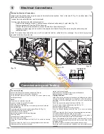
6 ELECTRICAL CONNECTIONS ....................................................................................................................10
Making the Electrical Connections ........................................................................................................10
7 COMMISSIONING AND TESTING ................................................................................................................10
Pre-commissioning ................................................................................................................................10
DHW ......................................................................................................................................................10
Central Heating .....................................................................................................................................10
Lighting the boiler...................................................................................................................................10
By pass and pump .................................................................................................................................11
Post Commissioning ..............................................................................................................................11
Handing over to the Householder .......................................................................................................11
8 FITTING THE CASING ..................................................................................................................................11
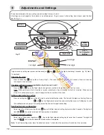
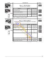
9 ADJUSTEMENTS AND SETTINGS ..............................................................................................................12
10 INCORRECT FUNCTION .............................................................................................................................17
11 GAS CONVERSION .....................................................................................................................................17
USER’S INSTRUCTIONS
Page
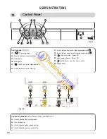
12- CONTROL PANEL ......................................................................................................................................18
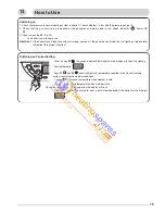
13- HOW TO USE ..............................................................................................................................................19
Switching on ........................................................................................................................................19
Switching on Central heating ................................................................................................................19
Switching on the Domestic Hot water ...................................................................................................19
Switching on the Domestic Hot water and Central Heating together ....................................................19
Stand by mode ......................................................................................................................................20
Turn off the boiler ..................................................................................................................................20
14 MAINTENANCE ............................................................................................................................................20
15 GUARANTEE ................................................................................................................................................20
16 PRACTICAL INFORMATION ........................................................................................................................20
17 GAS CONVERSION .....................................................................................................................................21
18 INCORRECT FUNCTION .............................................................................................................................21
19 TECHNICAL DATA .......................................................................................................................................22
This instruction booklet is especially designed for appliances installed in the The United Kingdom and The
Republic of Ireland
INTRODUCTION
The
CENTORA GREEN SYSTEM
is a fully automatic, wall mounted, low water content condensing system boiler. It
is a room sealed, fan assisted, balanced flued appliance providing central heating. It has electronic ignition and is
suitable for all modern electrical control systems. The boiler is designed for sealed systems only and a circulating
pump, expansion vessel together with a pressure gauge and safety valve are included within the boiler.
The standard horizontal flue kit is suitable for lengths 300 mm minimum to 600 mm maximum and includes an
elbow adapter that can be rotated through 360 ° . The horizontal flue can extend up to 3 metres using 1 metre
flue extension kits. 45 ° and 90° flue bends are also available as accessories.