23
Страница 1: ...system 30 c Manufactures N Model Type Gas Council N 200905821037 31 Centora Green System 24 Nat 41 980 12 200906822037 31 Centora Green System 30 Nat 41 980 31 GB IE U n i t 3 A T h o r n t o n R o a...
Страница 2: ...ors and windows to ventilate the room Shut the gas mains tap on the gas meter or the valve of the gas cylinder and call your Gas Supplier immediately If you are going away for a long period of time re...
Страница 3: ...S 7671 and document IGE UP 7 In the Republic the Republic of Ireland the installation should be carried out in accordance with the following codes of practice I S 813 Domestic Gas Installation the fol...
Страница 4: ...T FUNCTION 21 19 TECHNICAL DATA 22 This instruction booklet is especially designed for appliances installed in the The United Kingdom and The Republic of Ireland INTRODUCTION The CENTORA GREEN SYSTEM...
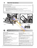
Страница 5: ...at sensor 42 Silencer 1 2 3 4 5 6 8 11 12 13 14 35 30 24 34 1 INSTALLER S INSTRUCTIONS 7 Fig 1 Fig 3 15 21 10 9 Fig 2 33 36 31 32 19 18 23 16 29 24 Display 27 Setting key 28 Setting key 29 Central Hea...
Страница 6: ...m The expansion vessel is pre charged to 0 7 bar 10 lb in 2 The vessel is suitable for systems up to 145 litres capacity For systems of greater capacity an additional expansion vessel will be required...
Страница 7: ...ulphur level contained in the gas should comply with the europ an Standards which are maximum 150 mg m3 for a short period in a year average level of 30 mg m3 during one year Electrical Supply The app...
Страница 8: ...e system should be carefully checked for leaks as frequent refilling could cause premature system corrosion or unnecessary scaling of the heat exchanger The pipe from the siphon 12 fig 1 should be con...
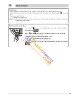
Страница 9: ...of 5 mm If the flue is a side exit installation then calculate the position of the hole with a slope of 5 mm metre towards the boiler from the terminal The flue should rise up slightly to the terminal...
Страница 10: ...rthing continuity DHW Open the main cold feed valve 40 Open all hot taps to purge DHW system Check for water soundness Check flow rate at the bath tap is set correctly see technical data Central Heati...
Страница 11: ...available in C H mode Post Commissioning Ensure system pressure has been set correctly Set all parameters of the boilers as shown in chapter 9 ADJUSTMENTS AND SETTINGS Set boiler thermostat and contro...
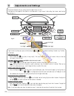
Страница 12: ...eter in a section Press on setting key key on the Left side to enter in modification mode The 2nd and 3rd digits are flashing Press on or on the Right side to select the correct value then press on Se...
Страница 13: ...ersion of display PCB 0 10 to 99 Flue type 2 1 FF variable speed Room thermostat is calling for heat 3 0 no 3 1 yes Theoretical position of the 3 way valve 4 0 DHW 4 1 CH DHW flow temperature in Celsi...
Страница 14: ...min 2 1 0 min 2 5 0 min Maximum Central Heating flow temperature 4 50 C 4 80 C CH anti cycling delay 8 0 0 min From 0 to 7 minutes by step of 0 5 min 8 0 5 min 8 2 5 min 8 5 0 min CH maximum output li...
Страница 15: ...erature is displayed in celsius degrees The 3 dots indicate that the combustion rate control is ON at maximum output X X Switching off the combustion rate control mode press once press once press once...
Страница 16: ...side times The display shows 906 which corresponds to the 18 kW which is the factory setting 9 section 9 06 18 kW press on setting key on the Left side one time the 2nd and 3rd digits flash together T...
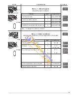
Страница 17: ...l Heating thermistor faulty open circuit 12 Central Heating thermistor faulty open circuit 18 Attempt to re light 20 Wiring problem 23 Fan speed too low 24 Fan control system defective 31 Communicatio...
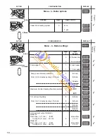
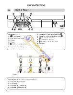
Страница 18: ...nge indicator Burner ON 35 Red indicator Lock out flame failure 36 Reset button 12 Connecting bracket Taps shown in Open position fig 21 37 Central heating flow isolating valve 39 Gas service tap 41 C...
Страница 19: ...ing Press on key 29 the green indicator 30 will light and the display will show the Heating flow temperature Keys 31 and 32 allow to adjust the temperature required in the Central Heating system regar...
Страница 20: ...and the burner will start 13 15 The manufacturer s guarantee is for 12 months from the date of purchase The guarantee is voidable if the appliance is not installed in accordance with the recommendati...
Страница 21: ...system and rise up the system pressure chapter 8 Close the heating flow isolating valve Don t forget to open it again when you will start heating Gas Conversion Incorrect Operation Helpful suggestions...
Страница 22: ...0 87 m3 h 31 ft3 h 1 m3 h 35 ft3 h Gas valve restrictor diameter without without Propane L P G G31 Gas rate C H max 1 94 kg h 36 ft3 h 2 21 kg h 41 ft3 h Gas rate C H mini 0 64 kg h 12 ft3 h 0 73 kg h...
Страница 23: ...23 U n i t 3 A T h o r n t o n R o a d I n d E s t a t e O f f H o c k n e y R o a d B r a d f o r d B D 8 9 H Q 0 1 2 7 4 4 8 8 3 8 8 w w w h e a t i n g s p a r e s 2 4 7 c o m...
Страница 24: ...ited MTS Building Hughenden Avenue High Wycombe Bucks HP13 5FT Telephone 01494 755600 Fax 01494 459775 Internet www chaffoteaux co uk E mail info uk mtsgroup com Technical Support Help Line 0870 241 8...