


12
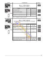
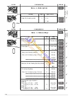
The boiler is delivered with a pre setting values described in menus 3 and 4.
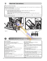
All settings can be changed by the installer or a qualified person. To gain access to the setting keys please, open the front
door P. (Fig. 17)
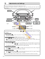
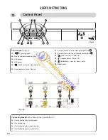
DISPLAY
1 st digit
2 nd digit
3 rd digit
Menu key
Setting key
To gain access to setting menus press simultaneously on
and
keys on the Right. side during 5 seconds. (fig. 18). Menu
1 is displayed.
Changing the menu :
Press on Menu key (
key on the Left. side) (Fig.17). The menu number is displayed for 3 seconds. Press on menu key
to change for the next menu.
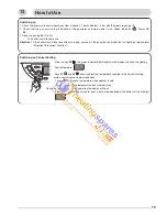
Changing section in a menu (available only for menu 3 and 4 :
Press on
or
key on the Right side to change from a section to the previous or the next in a menu.
Note : When you arrive at the last section of a menu, pressing on + key will change for the the 1st section. When you are
at the first section, pressing on – key will change for the last section of the menu.
Setting a parameter in a section
:
Press on setting key (
key on the Left side) to enter in modification mode. The 2nd and 3rd digits are flashing Press on
or
on the Right side to select the correct value then press on Setting key to valid
this modification and to get out from setting mode. The 2nd and 3rd digit stop flashing.
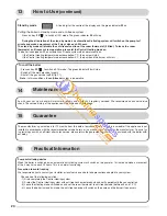
Recalling the basic configuration:
Select menu 3 or 4 then press together on
key on the Right side and setting key for more than 5 seconds. The digits will
flash CM
for a while to indicate that the operation is completed.
Erasing the default register :
Select menu 1 then press together on
+ key on the Right side and setting key for more than 5 seconds. The digits will
flash CM
for a while to indicate that the operation is completed.
Note : To exit from setting mode, leave the boiler for approx. 1 minute then the computer will switch back to user mode.
DISPLAY
Fig. 17
P
Right side
Left side
9
Menu
access
Key +/-
for Parameter
Setting
&
Adjustments and Settings