


3. Installation
3. Installation
3.5.1 DC connection high voltage danger notice
CAUTION
RISK OF ELECTRIC SHOCK
Do not touch an energized DC conductor. There are high voltages present when PV modules are
exposed to light causing a risk of death due to an electric shock from touching a DC conductor!
Only connect the DC cables from the PV module to the inverter as described in this manual.
CAUTION
POTENTIAL DAMAGE TO THE INVERTER DUE TO OVERVOLTAGE
The DC input voltage of the PV modules must not exceed the maximum rating of the inverter.
(see Section 9 “Specifications”)
Check the polarity and the open-circuit voltage of the PV strings before connecting the DC
cables to the inverter.
Confirm proper string length and voltage range before connecting DC cable to the inverter.
3.5.2 String sizing
For PV array sizing please refer Section 9 “Specifications” and utilize industry standard
string sizing techniques as specified by your local code.
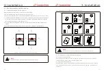
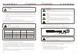
3.5.3 Recommended fusing section for each channel or connection
3.5.3.1 Maximum allowable amperage per fuse and channel
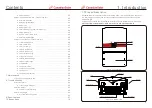
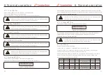
Figure
3.11 Shows sixteen (16) channels for connecting DC strings. Each channel is protected
by a fuse. The included fuses are rated at 15A. Changing fuse size could damage the fuse or
leave the module improperly protected. Do not change the fuse size.
Figure 3.11 Sixteen (16) channels in 2 sections
WARNING
If the amperage per connection is exceeded, the inverter could be damaged.
Ensure all wire sizing procedures are completed per local codes and
regulations.
Ensure the AC grid and DC PV array connections have enough separation
to prevent contact with each other.
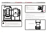
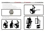
3.5.4 Process of connecting DC wires to terminals
3.5.4.1 Using fuse terminal
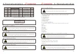
Figure 3.12 Fuse terminal
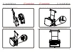
Loosen the screw to open wire cage. Strip cable insulation about ½ inch.
Check for proper string
voltage and polarity. Do not close fuse holder until commissioning
tests are completed.
Insert the wire and tighten screw to secure wire. Torque to 1.5-1.7Nm.
The
sizing
of
the
string
fuses
must
take
into
account
the
two
following
conditions
:
1).
The nominal current rating of the selected fuse must not exceed the maximum fuse
rating of the PV panels. Please refer to the applicable specifications for this value.
2).
The fuse rating is determined based on the PV panel string current and on the sizing
guidelines provided by the panel manufacturer or the local electrical code. In addition,
the maximum fuse rating must not exceed the maximum input current of the inverter.
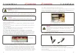
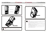
Figure 3.10 Fuse jumper bars
Canadian Solar Three phase inverters include an integrated wiring box which performs the
combining of DC strings. The fuses and fuseholders in the wiring box are not rated to carry
the current of multiple strings. Each DC string should be directly connected to the inverter.
When using field combiners, the provided jumper bars must be used.
.23.
.22.
jumper bars


