


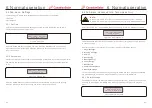


3. Installation
3. Installation
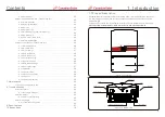
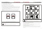
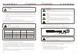
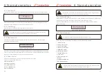
3.4 Wiring box configuration
The Canadian Solar U.S. Three Phase Inverter wiring box is designed for easy access to all
connection terminals, including monitoring communication ports. The wire box features a
spacious work area and pre-drilled 2 inch (ID) knockouts on the bottom and sides of the
cabinet.
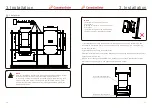
Figure 3.8 Inverter connection area of wiring box
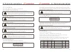
Parts
Connection
Cable size
Torque
#
from
Figure 14
above
1
2
3
4
5
6
Table3.1 Connections list
DC terminal
Ground terminal
Grid terminal
RS-485 terminal
RJ45 terminal
COM terminal
PV strings
DC and AC ground
Grid
Communication cable
Communication cable
Wi-Fi/GPRS stick
12-6 AWG
12-4 AWG
8-2 AWG
22-12 AWG
Network cable
NA
30 in-lbs
26 in-lbs
26 in-lbs
3.5-5.3 in-lbs
NA
NA
7
DC surge protection
device
NA
NA
NA
1
2
3
4
5
6
7
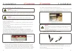
WARNING
DO NOT connect the PV array positive or PV array negative cable to ground.
This can cause serious damage to the inverter!
WARNING
MAKE SURE the polarity of the PV array output conductors matches
the DC- and DC+ terminal labels before connecting these conductors
to the terminals inside the inverter wiring box.
See Section 9 for acceptable wire sizes and Figure
10.1 for screw
torque
values
for
the
AC
and
DC
connections.
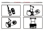
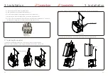
Both the DC and AC ground wires can be connected to the grounding terminal block (see
Figure 3.9).
Figure 3.9 Grounding terminal block on the metal bracket
Requirements for the PV modules per MPPT input:
● All PV modules must be of the same type and power rating.
● All PV modules must be aligned and tilted identically.
● The open-circuit voltage of the PV array must never exceed the maximum input voltage of
the inverter, even at the coldest expected temperature. (see Section 9 “Specifications” for
input current and voltage requirements)
● Each string connected to a single MPPT must consist of the same number of series-
connected PV modules.
3.5 DC connection
WARNING
Before connecting the inverter, make sure the PV array open circuit
voltage is within the limit of the inverter. Otherwise, the inverter could
be damaged.
Maximum 1000Vdc
for CSI-50KTL-GS-FL , CSI-50KTL-GS
,
B
-B
CSI-60KTL-GS
, CSI-66KTL-GS
-B
-B
.21.
.20.


