


6
PART 1 GENERAL INFORMATION
1.1
INTRODUCTION
The
Dynaforce®
is a condensing forced draft appliance utilizing
a premix power burner based on a push through design which
offers several venting options. Heat output is controlled by a one
to one air/gas ratio control gas valve which provides seamless
modulation. The Dynaforce® provides central heating or
domestic hot water at working pressures up to 160 PSI. It is
designed for use with a fully pumped and pressurized system.
The boiler/water heater will automatically modulate to provide
heat outputs between 100% and down to 20%.
The Dynaforce® works on the principle of differential pressure.
The operation of the fan will generate a differential
pressure
,
which the gas/air ratio control gas valve will match on the gas
side. The steady state efficiency is maintained across the entire
range of modulation. Air and gas are metered in precise
proportion (1:1 Ratio) to modulation signal, allowing combustion
characteristics which determine efficiency to remain the same
over entire operating range.
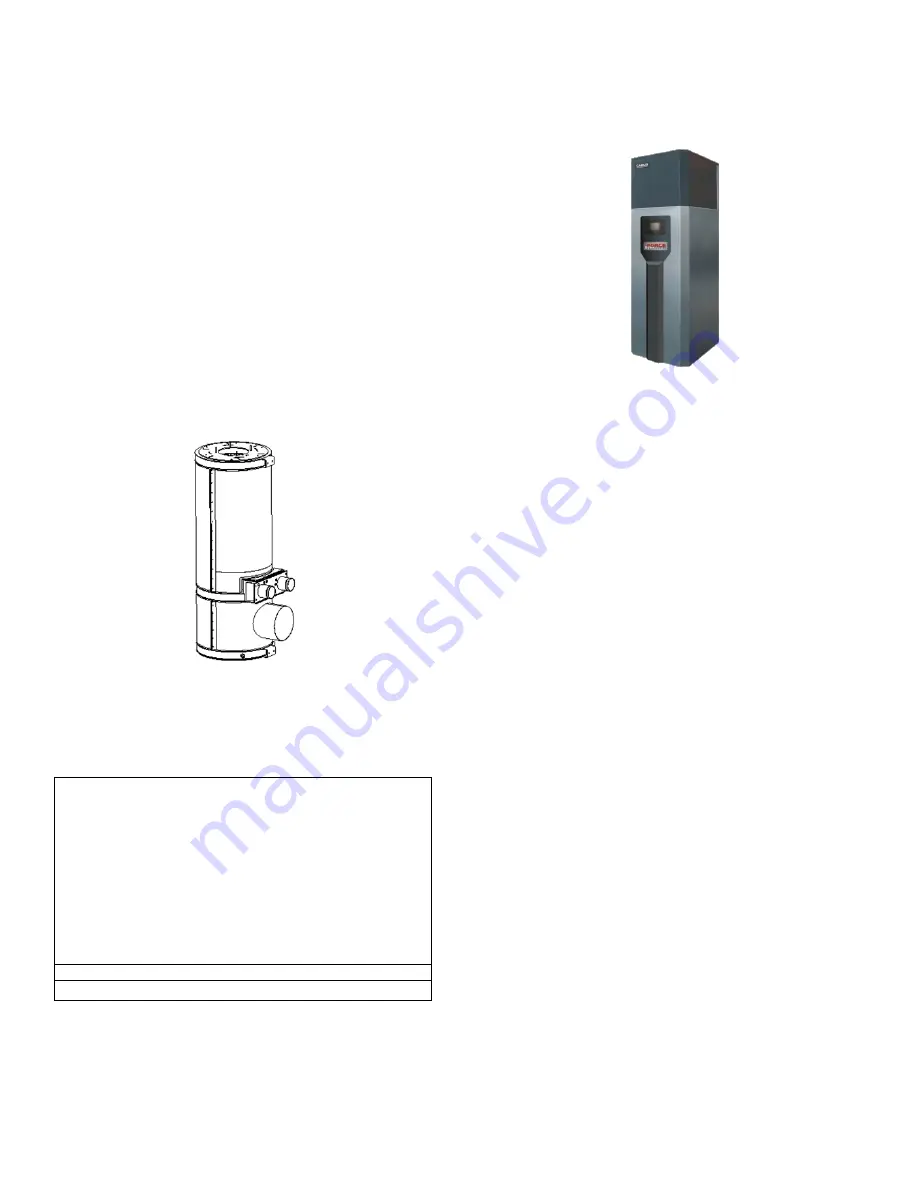
Figure 1: Dynaforce
1.2
SPECIAL INSTRUCTIONS TO OWNER
This manual supplies information for the installation, operation
and servicing of the appliance. It is strongly recommended that
this manual be reviewed completely before proceeding with an
installation
CAUTION
It is important that all gas appliances are installed by a
qualified installer/technician that is trained by Camus®
Hydronics. It is in your own interest and that of safety to
ensure that all local codes, and all the following “NOTES” and
“WARNINGS” are complied with.
Installing, servicing or adjusting this appliance should be
performed only by a qualified installer/technician that is
trained by Camus® Hydronics. The serviceman must utilize
a combustion analyzer with CO
2
, CO, and draft gauge, to set
the appliance according to Camus® Hydronics’
recommendations, prior to commissioning.
NOTE
RETAIN THIS MANUAL FOR FUTURE REFERENCE
1.3
CHECKING EQUIPMENT
Check for signs of shipping damage upon receiving equipment.
Pay particular attention to parts accompanying the boiler, which
may show signs of being hit or otherwise being mishandled.
Verify total number of pieces shown on packing slip with those
actually received. In case there is damage or a shortage,
immediately notify carrier.
Figure 2: Checking the Dynaforce
Do not attempt to pry any panel off. To begin disassembly, you
must first remove the two ¼” machine screws from the top of the
lid. Only then will you be able to remove the lid and disassemble
the three outer panels.
Once you have removed the lid carefully check and confirm that
all ¼” copper tubing connections are intact and have not broken
or loosened in shipment. Leaks at any connections on these
lines will result in erratic appliance operation.
1.4
HOW IT OPERATES (SEQUENCE OF
OPERATION)
1 Supply power connection as per table 10.
2 The power switch is placed in the “ON” position.
3 120 VAC power is supplied to the control transformer.
4 24 VAC is supplied to the ignition module and low voltage
controls for all models.
5 After the appliance water pump starts, flow is proven by the
flow switch and water pressure switch. The water pressure
switch is set to close at 30 PSI and is installed in the unit.
The flow switch is to be mounted in a tee at the outlet of the
appliance. Take care to properly trim the flow switch
paddles so as not to jam the switch in the tee. The normally
open dry contacts in the low water cutoff (LWCO) are to be
wired in series with the normally open contacts of the flow
switch. Locate the probe type LWCO in the piping above
the highest point of the heat exchanger. The low water
cutoff and flow switch are shipped loose. In all cases check
with local codes.
6 The Dynaforce® controller receives a call for heat via the
remote operator contacts and the Demand parameter reads
Central Heating or DHW.
7
DR 300 – DR 1000:
The Dynaforce® controller energizes
the pump contacts and starts to ramp up the voltage to the
electrically commutated DC motor of the combustion fan
after internal safety checks are satisfied.
DR1200 – DR5000:
The local thermostat energizes the
motor stop/start relay which closes the initiate contacts to
the variable frequency drive (VFD) which starts to ramp up
the frequency to the 230V 3 phase motor of the combustion
fan. If the VFD is not in fault mode the frequency will
accelerate at the preprogrammed rate towards maximum
speed using the modulating signal provided by the on board
modulating control or the remote operating system.
8 If temperature high limit, water flow and airflow switches are
closed the fan will run at pre-purge speed until the pre-
Содержание DRW1000
Страница 2: ...99 0171 REV 0 9...
Страница 35: ...35...
Страница 48: ...48...
Страница 67: ...67 PART 12 EXPLODED VIEW 19 1 2 3 4 5 6 7 8 9 10 11 12 13 14 15 16 17 18 20...
Страница 68: ...68 21 22 23 24 26 35 34 33 32 31 30 29 28 27 25 36 37 38 39 40 42 43 56...
Страница 75: ...75 PART 13 ELECTRICAL DIAGRAMS...
Страница 76: ...76...
Страница 77: ...77...
Страница 78: ...78...
Страница 79: ...79...


