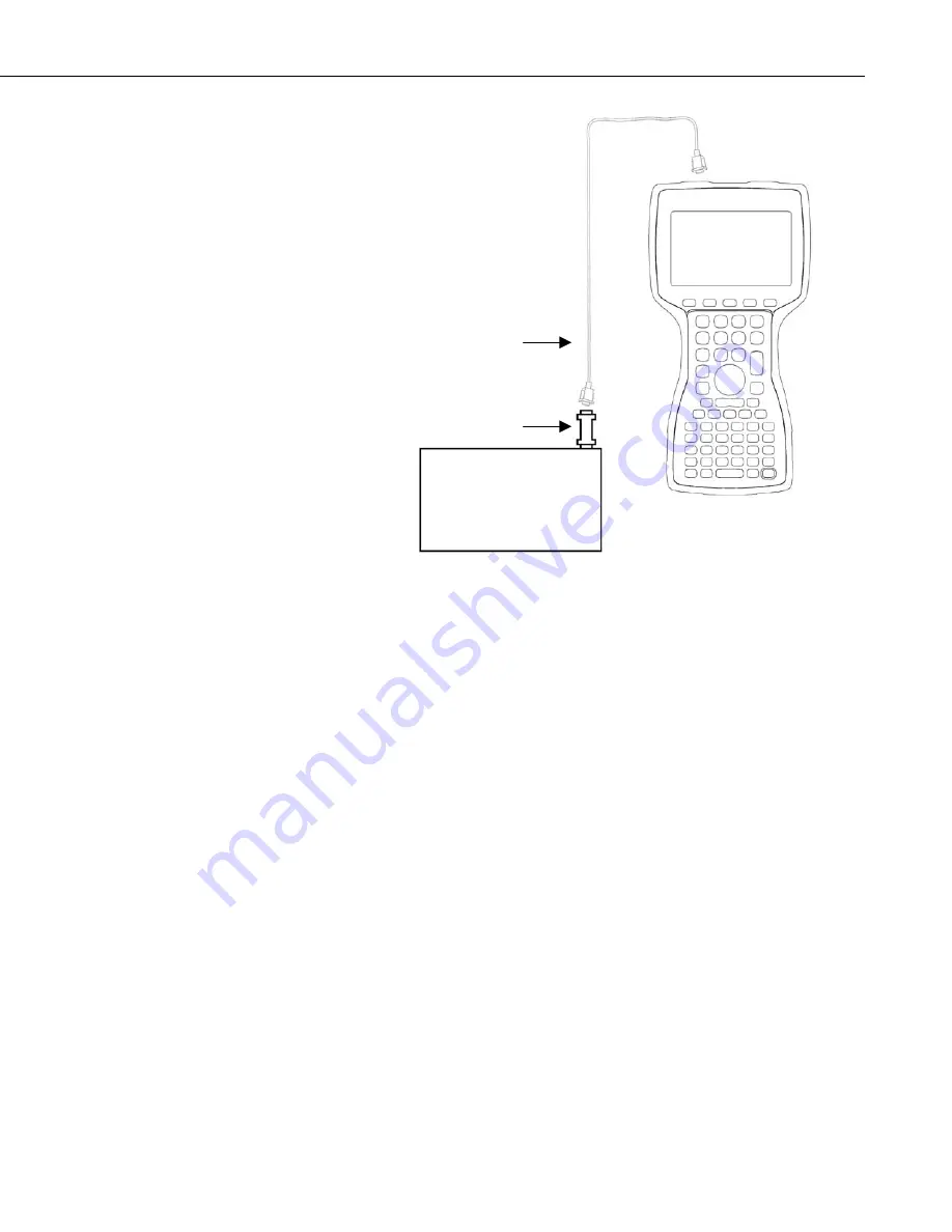
PConnectCE for the Allegro CE
5
Note that one side of the connector is labeled Datalogger, and the other side is
labeled PDA. If the connections are reversed, communication with the
datalogger will fail.
3.2 RF400 Radio Communication
Two RF400 radios can be used to communicate with the datalogger using the
Allegro. With this setup, the PDA to CS I/O connector is not used.
At the datalogger site, the CS I/O ports of the RF400 radio and the datalogger
are connected using an SC12 or similar cable. Power for the RF400 is supplied
by the datalogger’s CS I/O port pin 8, which supplies 12 V.
The Allegro is connected to the base RF400 radio by using an RS-232 null
modem cable between the Allegro’s serial connection and the RF400’s RS-232
port. Typically, this is accomplished by using the Allegro’s standard
communication cable, with a null modem connector at the end, connecting to
the RF400’s RS-232 port. Depending upon the type of null modem cable used,
a gender changer may be necessary. An external power source will be needed
for the RF400 base radio, since it cannot be powered by the handheld device.
Cables, gender changers, and power supplies can be purchased from local
suppliers or from Juniper Systems. Campbell Scientific offers a Null Modem
Cable Kit (DB9 Male to DB9 Male, P/N 14392) for connecting a handheld
device to the RF400 base. Two gender changers (P/N 14393) may be required
for use with a customer-supplied null modem cable. The RF400 Base Station
Kit (P/N 14220) provides an AC to 12V DC transformer for the RF400. The
Field Power Cable (P/N 14291) provides a 12V DC barrel plug on one end for
Datalogger
Connection Serial Cable
(purchased separately)
“PDA to CS I/O” Adaptor
(supplied with
PConnectCE
)
Allegro CE


