SECTION 3. INSTRUMENTATION INSTALLATION
3-11
4.
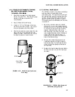
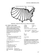
With the power switch "OFF", connect the
power cord to 110V AC. Connect the serial port
to the computer's serial port using an SC25PS
cable for a 25-pin serial port, or a PN7026 cable
for a 9-pin serial port. Toggle the power switch
to "ON" to operate the RF232.
MADE IN THE
USA
AC INPUT
57 - 63 Hz
FOR USE AT 100 120
230-240
JUMPER
1&2
1&3
1&2
1&3
2&3
2&3
1&4
1&5
1&4
1&5
APPLY AC
MAX (CURENT)
FUSE RATING
.5A
.25A
!
EXTERNAL FUSE RECOUNTER
EXIT
IHB12-1.7
OUTPUT:
12DC AT
1.7 AMPS
I P
POWER
INTERNATIONAL
2N3055
MEXICO
92109
+12V
FCC ID: ATH90F0233420050
E.F.JOHNSON CO. U.S.A.
DL 3420
E.F. JOHNSON CANADA INC.
mfg by E.F. JOHNSON USA
DOC T.A. 89178
Serial No3400T144A 17858
FIGURE 3.3-6. RF232 Base Station
Installation
3.3.6 MD9 MULTIDROP INTERFACE
The MD9 Multidrop Interface enables
communication with one or more
MetData1s/dataloggers and the computer over
a single 75 ohm coaxial cable. An MD9 network
can be connected directly to a PC, or can be
connected to a telephone modem (refer to the
MD9 Manual) and accessed remotely.
Total coax length may be up to three miles.
Since each MD9 attenuates the signal 0.2 db,
the maximum length depends on the number of
MD9s in the network (refer to the MD9 manual).
Coaxial cable and BNC connectors may be
ordered from CSI, or purchased locally (Belden
Type 9100 RG59/U or equivalent). Call Belden
Wire and Cable at (317) 983-5200 for the name
of a local distributor.
Installation requirements depend on the type of
cable that is used, and how it is installed (direct
burial, conduit, etc.). In general, follow state
and local electrical codes.
3.3.6.1 MD9 Multidrop Interface at the
MetData1
1.
Remove the four screws that attach the lid
to the MD9. Remove the lid. Remove the
center screw from the circuit board.
Carefully remove the circuit board.
2.
Mount the lower half of the case into the
MetData1 using the inserts and screws
provided. Replace the circuit board and
center screw.
3.
Set the dip switches on the circuit board to
the appropriate Station ID (Table 3.3-2). Each
MD9 must have a unique ID; address 1 is
usually used for the MD9 at the computer,
address 2 for the next MD9, address 3 for the
next MD9, etc. The default baud rate is 9600,
which can be changed with the jumpers next
to the dip switches (Table 3.3-2).
4.
Replace the lid.
5.
A “pop-out” plug is provided adjacent to the
AC/Solar connector for mounting the
coaxial bulkhead connector into the
enclosure as shown in Figure 3.3-5.
Remove the “pop-out” plug by pushing it out
from inside the enclosure with a screw
driver. Wear gloves while doing this to
protect your hands when the plug gives
way. Install the coaxial bulkhead connector.
Attach the short coaxial cable to the MD9’s
coax connectors to the inside end of the
bulkhead connector. Attach the main
coaxial cable to the outside end of the
bulkhead connector. Wrap the outside
connection with the provided self-
vulcanizing rubber.
6.
Route the coaxial cable(s) to the MD9.
Connect the cable(s) to the MD9 using the
BNC "T" provided. The first and last MD9s
of the network must be terminated with 75
ohm Coax Terminators (Model MD9CT) to
prevent signal reflection.
3.3.6.2 MD9 Multidrop Interface at the
Computer
Connect the MD9 and the SC532 9 Pin
Peripheral to RS232 Interface to the computer
as shown in Figure 3.3-8.
1.
Connect the SC532 to the computer's serial
port using an SC25PS cable for a 25-pin
serial port, or a PN7026 cable for a 9-pin
serial port. Connect the MD9 to the SC532
with an SC12 cable.
2.
Route the coaxial cable to the MD9;
connect the cable and an MD9CT to the
MD9 using the BNC "T" provided.
Radio
Antenna Cable
12V and G
Terminals
Power
Switch
Serial
Port


