background image

26

Important: Always be careful when focusing thick material, not to allow material to collide with the lens 

housing. This can cause serious damage to the laser machine.

Lens Replacement

Lenses are one of the few parts of a laser machine that need regular maintenance, primarily regular clean-

ing. Lens cleaning is simple if done often, difficult or not possible if rarely done.

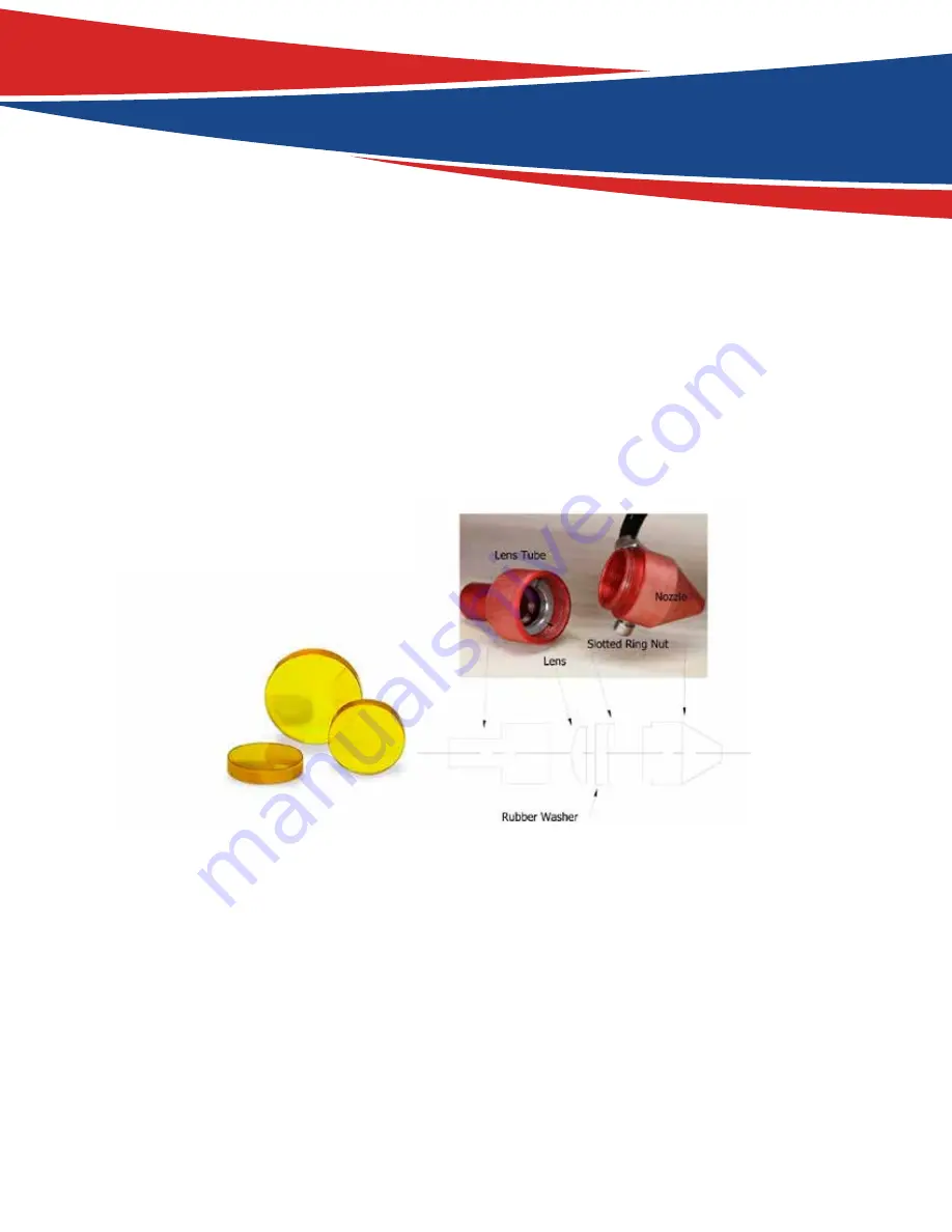
The lens is small, about 20 mm across, with 2 distinct sides, one flat and one convex or curved out. 

When 

reinstalling, the curved side always faces the laser path, away from the working platform.

 As illustrated 

above, the lens assembly consists of 2 main parts, the lens tube (also known as the lens housing) and noz-

zle, then 3 parts inside the lens tube. The lens, washer and slotted ring nut. To remove lens for replacement 

or cleaning, loosen the friction set screw on the main lens housing holding the lens tube in place. After 

loosening set screw the lens tube should slide out of the housing. Separate the lens tube from the nozzle 

like the illustration shown in the illustration above. Your laser tool box came with a tool for removing the 

slotted ring nut. The tool looks more like a scraper than a screw driver. Its width is designed to fit inside the 

lens tube and fill the slots. Be careful not to let the blade tip slip and scratch the lens. Once the slotted ring 

is out, the rubber washer will keep the lens pressed against the lens tube. Using a pencil with eraser, insert 

the eraser end into the laser tube and push out the lens. Both lens and washer will fall out the large end.

At this point the lens can be replaced or cleaned. Different size lens can be inserted as well, just be aware 

that a 4” lens has a different focus point than a 2” lens. The beam width increases with focal length and 

may require a nozzle with a larger opening. Handle the lens carefully, using acetone or lens cleaner/wipes 

to clean the flat side. Make sure to place the flat side down towards the working platform when reassem-

bling, curved side always faces the laser beam. Lens first, washer and then ring nut. Don’t over tighten 

ring nut, just snug it up against the washer, and then a quarter turn more. Burned lenses are a common 

Содержание Qustom Laser CFL-Q2012K

Страница 1: ...CFL Q2012K INSTALLATION MANUAL ...

Страница 2: ...ce Pág Pág Pág Pág Pág Pág Pág Installation Guide The Control Panel Set the layer parameters Alignment Standards of Optical Path Safety Materials for you and your Laser Machine Maintenance Schedule 4 6 10 13 21 8 27 ...

Страница 3: ...ecially ed ited this manual in order for you to learn the operation and maintenance of the machine We also took many real object photos in this manual to show you the installation adjustment and operation process The user should read this manual in detail before us ing because it will provide in detail the setup use and maintenance of your brand new CFL Q2012K ...

Страница 4: ...le in operation The operator should observe the machine carefully while working and in case of emergency must cut off the power or press the emergency shut off button Ensure that processing material and emissions conform to local laws and regulations The user should consider carefully whether the materials are suitable for laser cutting engraving for safety There are high voltage and other potenti...

Страница 5: ...5 Appearance of the Machine front Back View ...

Страница 6: ...pump anymore There are mainly five steps to get started 1 Open the water tank lid you will find the water inlet Pour water into the water tank and fill the tank We suggest using purified water or distilled water with temperatures under 35 degrees 2 Install the Exhaust Pipe Screw in the exhaust pipe fixture fasten the rings after you put the pipe on the fixture Then lead the other end of the pipe o...

Страница 7: ...ith a USB data cable in which you are able to connect to a laptop If a Wi Fi connec tion is preferred connect the machine into the Wi Fi interface and connect the machine to the network 4 Connect the power Connect the power cable into the machine and connect the cable into a 110V outlet ...

Страница 8: ... water Then you could start firing the laser Safety Materials for you and your Laser Machine The CFL Q2012K uses high heat to cut or etch a given material Some materials respond to this method successfully while others don t It is important to know the materials you are working with since some like PVC are easy to cut but give off a chlorine gas that s not healthy for humans or the machine Below i...

Страница 9: ...am often used for RC planes EPM Gator foam foam core gets burned and eaten away compared to the top and bottom hard shell Other Cloth leather suede felt hemp cotton Paper Rubber only if they do not contain chlorine Teflon PTFE Polytetrafluoroethylene Wood MDF balsa birch poplar red oak cherry holly etc Materials that can t or should not be cut Metals Polycarbonate PC Lexan due to the fumes any mat...

Страница 10: ...urrent running layer or set the power of Pulse Key Min Power Set the min laser power of the current running layer Start Pause To start or pause the work Left Right Arrow Moves the X axes or the left right cursor Up Down Arrow Moves the Y axes or the up down cursor Z U Buttton The Z U key can be pressed when the system is idle or the work is finished On pressing this key it will show some entries i...

Страница 11: ...idle double click the layer then users can change the layer s parameters and the changing would be saved Working Number To accumulate the work number of the current file File Dimension Displays the dimension of the current file Net status Displays the connecting status of the Ethernet Running Status Displays the current status of the machine such as Idle Run Pause Finish etc Running Progress Bar D...

Страница 12: ...s to change the value then push the Enter key to save the change push the Esc key to exit from the change Max Min power keys Push the Max Power or the Min Power keys when the screen is on the main screen shown below A B When Z U key is pushed the green block can move up and down to denote the changing item then Y keys and X keys can be used to change the value ...

Страница 13: ...irst layer then the Y keys can be pushed to select the intent layer at that time the user can push Enter key to check the selected layer s parameters illustrated below User can push Z U Keys to move the green block on the intended parameter and then you could change the parameter if needed OK to validate the change and Esc to invalidate the change ...

Страница 14: ...e Enter key to display the sub menu Z move When it is highlighted on Z Move item X keys can be used to move the z axes U move When the green block is on U Move item X keys can be used to move the u axes Axis reset When the green block is on this item push the Enter key to show as below Push the Y Keys to move the cursor to one of the entry then push Enter key to restart the selected axis the scree...

Страница 15: ... item is manual then pushing the direction key one time the corresponding axes will move a fixed length unless the scope is overstepped Laser set When the green block is on this item push the Enter key to show as below Push Z U key to move the green block and when the green block is on the Mode item push X keys to select the anticipant value Continue or Manual When Continue item is selected then t...

Страница 16: ... If you select Yes the system will use the multiple origin logic and the Origin key on the keyboard become invalid In such a case the parameter of each origin must be set in the menu as follows Origin Enable 1 2 3 4 after the multiple origin logic is enabled the four origins can independently be prohibited and enabled Set Origin 1 2 3 4 after the multiple origin logic is enabled you can stop the c...

Страница 17: ...l below IP Setup When the green block is on this item push the Enter key to show as below Push Z U key to move the changing item then push X keys and Y keys to change the value when all the IP value and the Gateway value are changed push Enter key to validate the change or Esc key to invalidate the change ...

Страница 18: ...witch etc When the inputis validated the color frame will be green otherwise it ll be gray Screen Origin If the Screen Origin item is pressed the system will show as below There are four entries to be selected Top Left Top Right Bottom Left and Bottom Right When one is se lected the previewed graph on the screen would be opposite based on X or Y direction Make sure the Origin location is set to TO...

Страница 19: ...ed file Delete To delete the selected file in the memory Copy to Udisk To copy the selected file to Udisk When showing this menu the system would read the memory file first the file name and the work times would be listed in the area and the selected file is previewed in the bottom right area Y keys could be used to move the cursor on the file name list When the cursor is on a target file name pre...

Страница 20: ... To format memory speedily and then all the files in memory will be deleted Format drastically To format memory drastically and then all the files in memory will be deleted Total The total running times of all the files U Disk File If the Udisk entry was pressed the system will show as seen below and the operation method is all the same as above Read Udisk Read the file list in the Udisk Copy to m...

Страница 21: ...p 1 First to ensure laser beam from laser tube to the center of the first mirror 1 Step 2 Add a piece of tape onto the fixture of the mirror in order to mark where the beam is pulsing press pulse and adjust the mirror accordingly to the center of the beam with special attention In order to pre vent the laser radiation wounding with a piece of cardboard first to test the approximate location of the...

Страница 22: ... are not superposition adjust the screws on the back of the 1 mirror to make the laser fire on the same position as the first spot Step 5 Repeat the second to the fourth steps until the two spots overlap completely Moreover the spots should be in the center of the hole ...

Страница 23: ... the nearest position from 2 mirror press pulse choose suitable power get a spot on the paper Step 7 Move away the laser head to the position farthest from the 2 mirror press pulse first to detect the approximate location of laser with a piece of cardboard to prevent wounding get another spot ...

Страница 24: ...aper on the 3 reflector press pulse get a spot on the paper If it is in the center of light hole then pass Step 11 If the laser light is not in the center of light hole as below figure In the left Figure the spot is upper and right biased Top to bottom bias can only raise or lower the laser tube Inside and outside bias only move the laser tube in or out to adjust In this case it is essential to lo...

Страница 25: ...g paper or other flat materials on the worktable Press the Up down arrow on the control panel to adjust the distance from the paper to the laser head to about 20mm Secondly press the PULSE button on the control panel then the laser will fire and make a spot on the paper Then adjust the distance closer to make another spot on the paper then adjust to another distance to make more spots Thirdly comp...

Страница 26: ...om the nozzle like the illustration shown in the illustration above Your laser tool box came with a tool for removing the slotted ring nut The tool looks more like a scraper than a screw driver Its width is designed to fit inside the lens tube and fill the slots Be careful not to let the blade tip slip and scratch the lens Once the slotted ring is out the rubber washer will keep the lens pressed a...

Страница 27: ...s the cleaning solvent Use a lens tissue or cotton tipped swabs Q Tips to apply the solvent Len wipes with alcohol free solution will also do the trick Do not scrape the lens Use the solvent to dissolve the dirt from the lens surface Only use a soft swirling motion when applying the solvent Use a dry swab in soft swirling motion while evaporating the solvent Use as many swabs as needed to result i...

Страница 28: ...end of the gantry rail This mirror should be cleaned at least every two months Use the same directions as found for Mirror 3 Mirror 1 This mirror is located directly in front of the laser tube This mirror should be cleaned at least every three months Use the same directions as found for Mirror 3 Laser tube output coupler lens This lens is located inside the output end of the laser tube This lens s...

Страница 29: ...e bearing alignment or damage to the matching bearings There are many laser machine designs but the method of changing the belt tension should not be too difficult It is normally a method of tightening a screw and then applying a lock nut to keep the screw in place Add or Change Water and Clean the Water Tank The water cooling system is built in for this machine It is a sealing system It is not ne...

Страница 30: ...30 Storage of the laser Store the laser in a clean dry warm location with no vibrations ...

Страница 31: ...e off Make sure power supply is well connected if it works Correct the parameters according to software operating manual 2 Working with a nonstop laser Mainboard Parameters are off Correct the parameters according to software operating manual 3 Desultory light when work ing Check if water is circulating Voltage may not be stable Clean Water tank pump and pipe Add Regulator for the laser machine 4 ...

Страница 32: ...ustomlaser com TECH SUPPORT support us camfive com SALES sales us camfive com CALIFORNIA 626 855 4515 219 S 3rd Ave Suite 3 Los Angeles CA 91746 Florida 407 851 5525 1629 Prime Ct Suite 700 Orlando FL 32809 ...

Отзывы:

Похожие инструкции для Qustom Laser CFL-Q2012K